Desktop Lathe
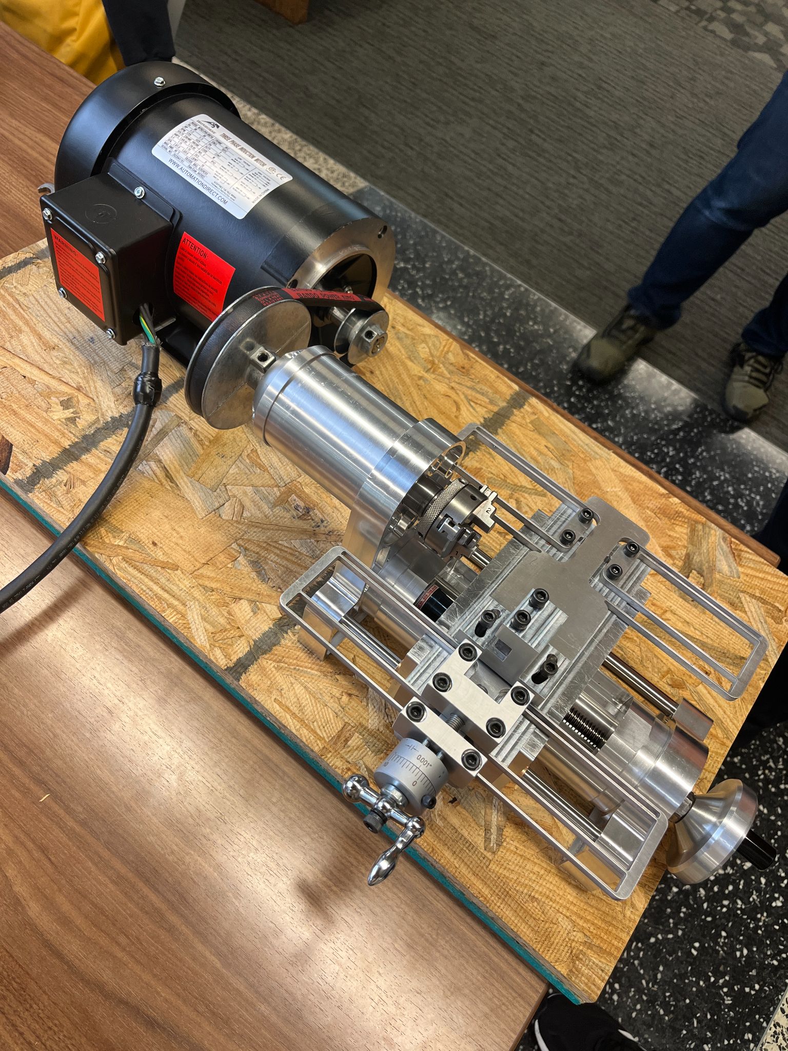
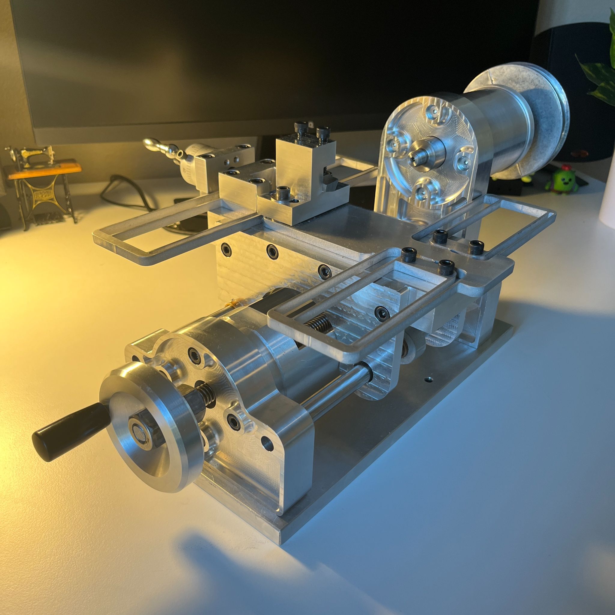
In this course on precision machine design, our group had to design and machine a desktop lathe. We designed and machined a spindle, derived homogeneous transformation matrices, designed flexure mechanisms, selected a belt and pulleys, and made alterations to pre-machined parts.
Spindle Design and Machining
The spindle is an important part of a lathe because it converts a motor's relatively sloppy rotational motion into a robust and stable rotational motion. It can be designed to withstand large loads and maintain a low runout, which are important variables for accurate and repeatable lathe work.
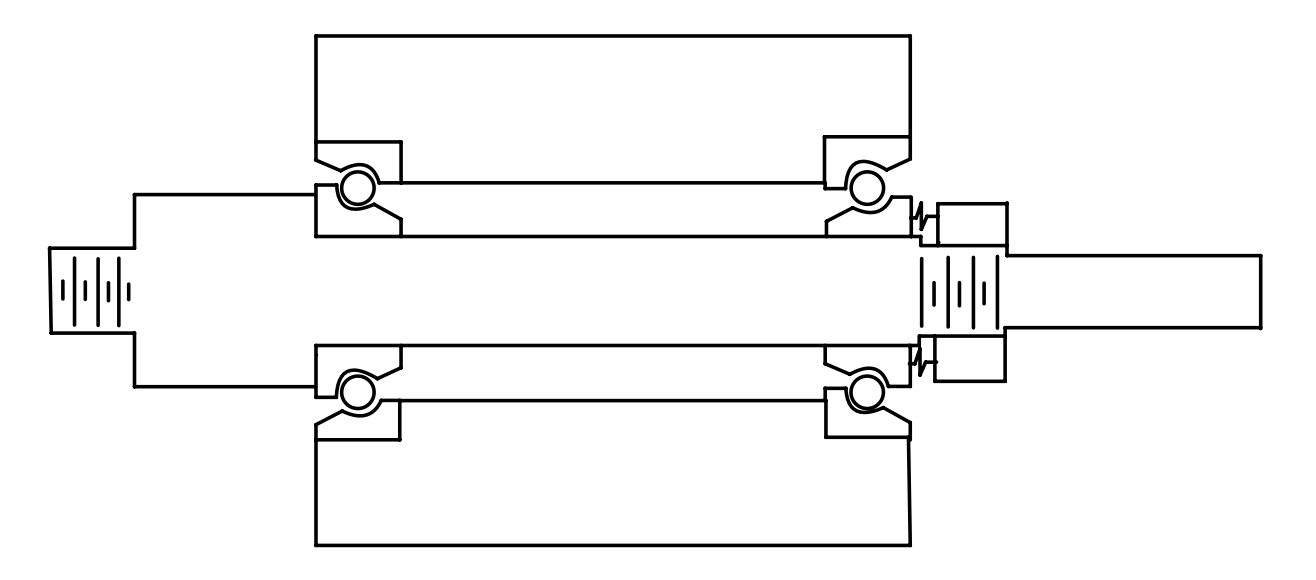
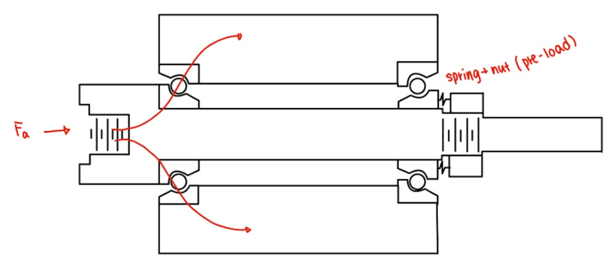
When designing the spindle, we first needed to know the speeds and loads it would be required to handle. We then chose the bearing configuration with consideration of the machinability of the shaft and housing, the axial and radial constraints, and the bearing pre-load method. With that figured out, we were able to choose the appropriate bearings, in this case, we chose angular contact bearings which can take high axial and radial loads as well as high rotational speeds.
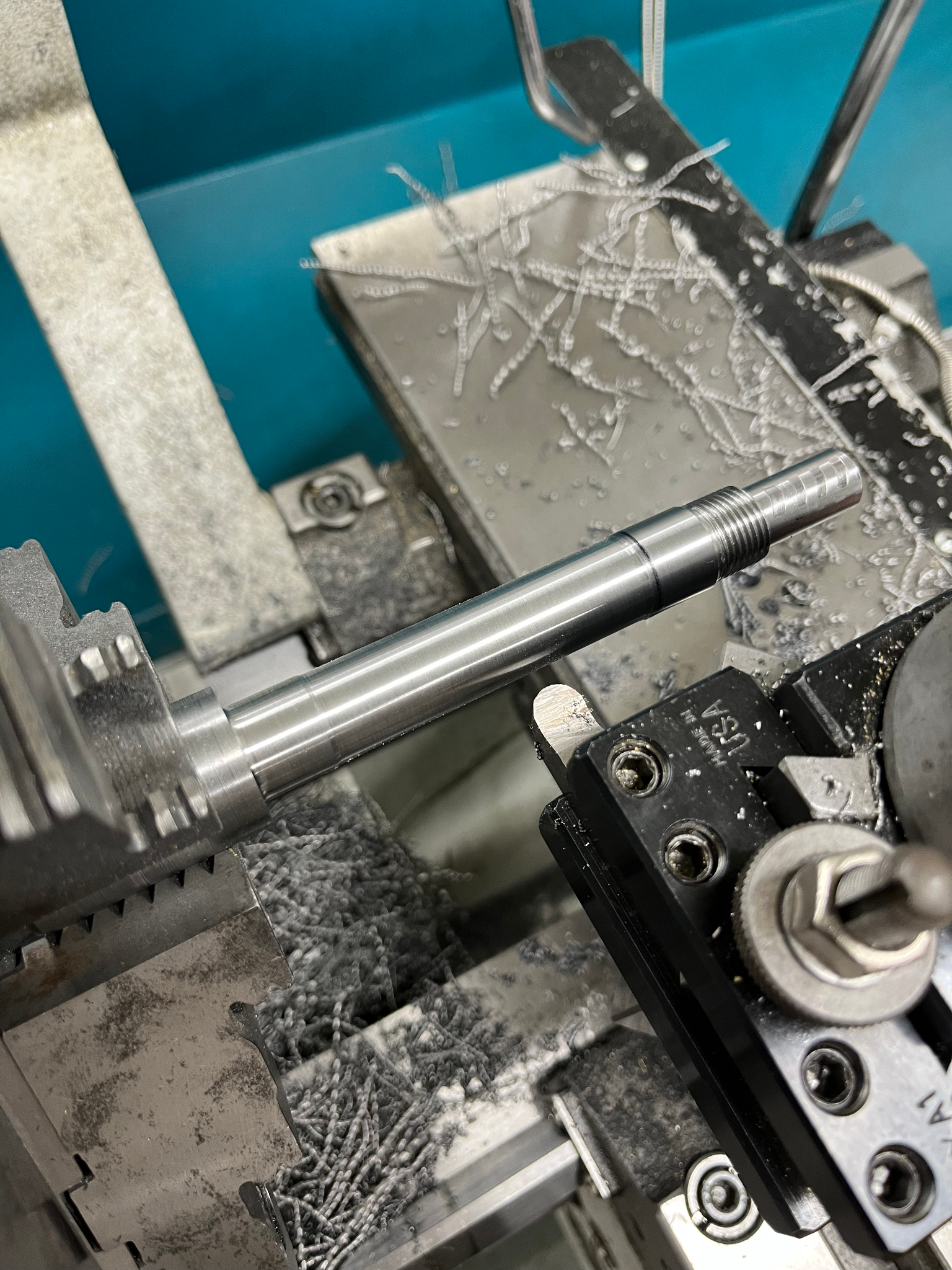
The most important part of the machining process for the housing and the shaft was to keep concentricity and runout as low as could be achieved. This was done by minimizing the number of fixturing and dial indicating for every re-fixturing.
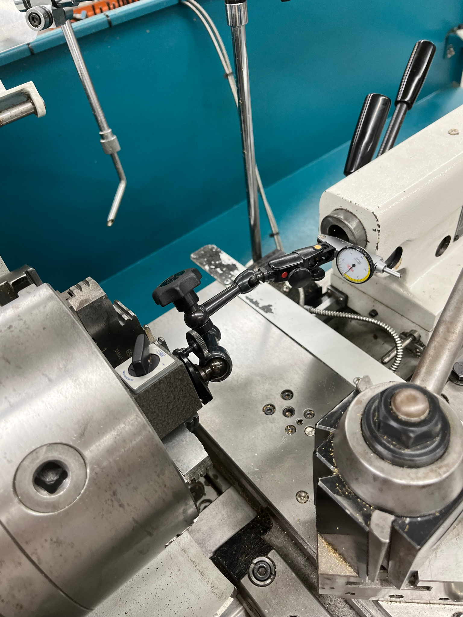
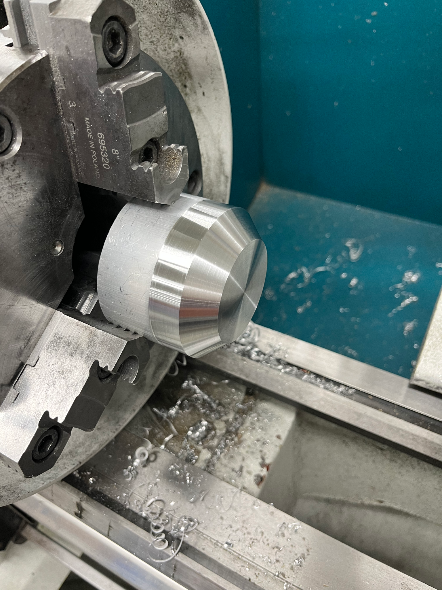
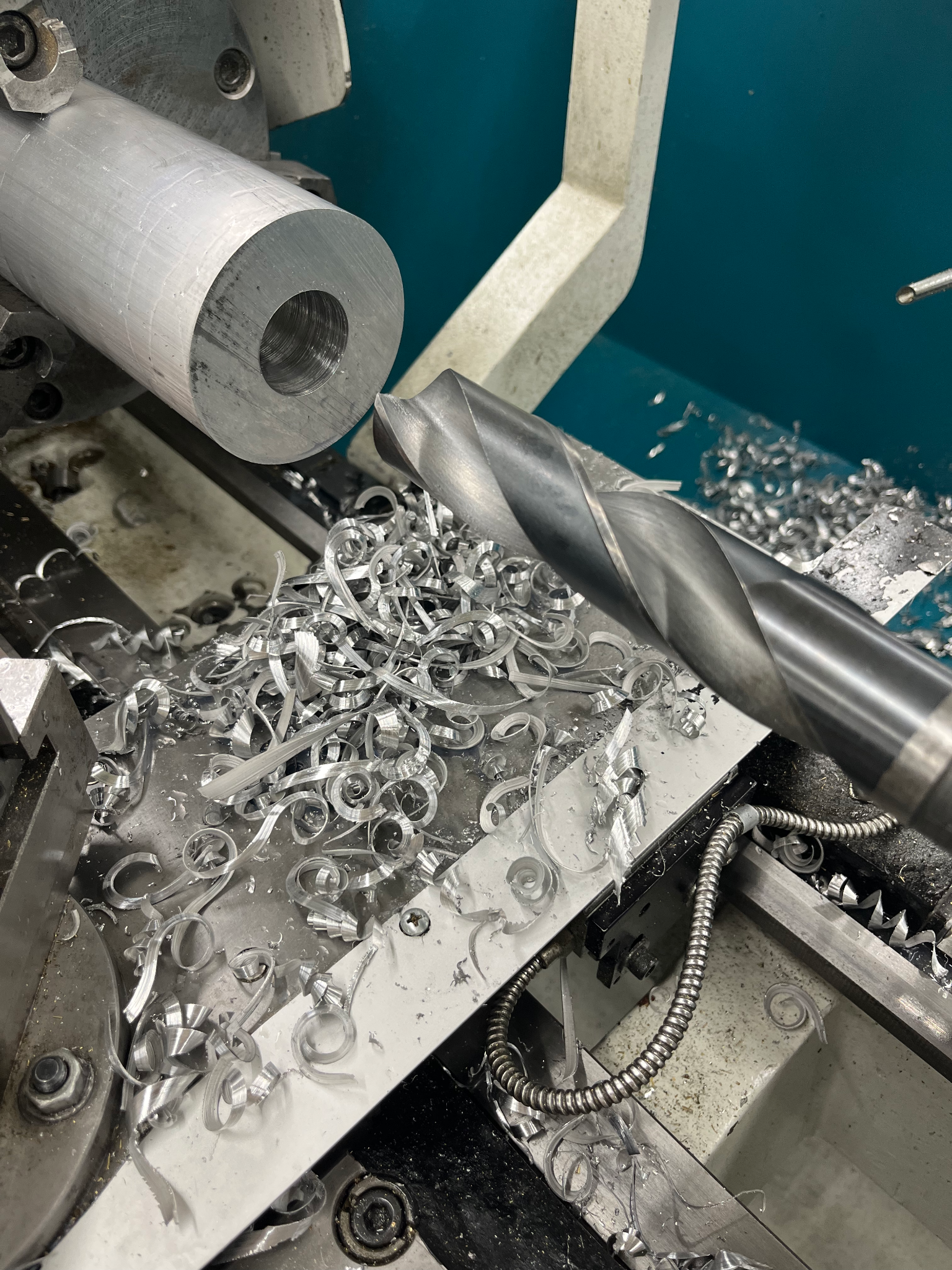
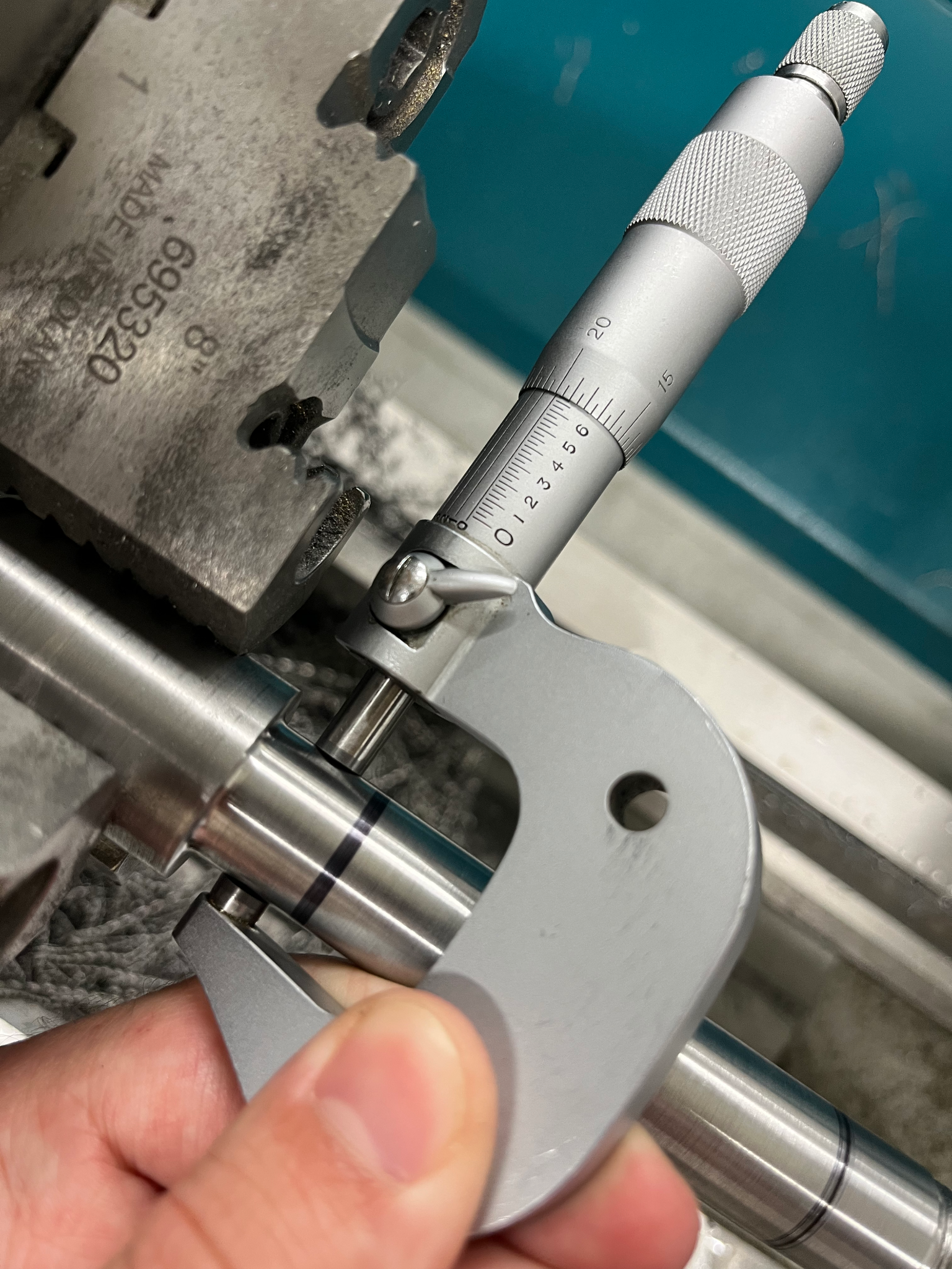
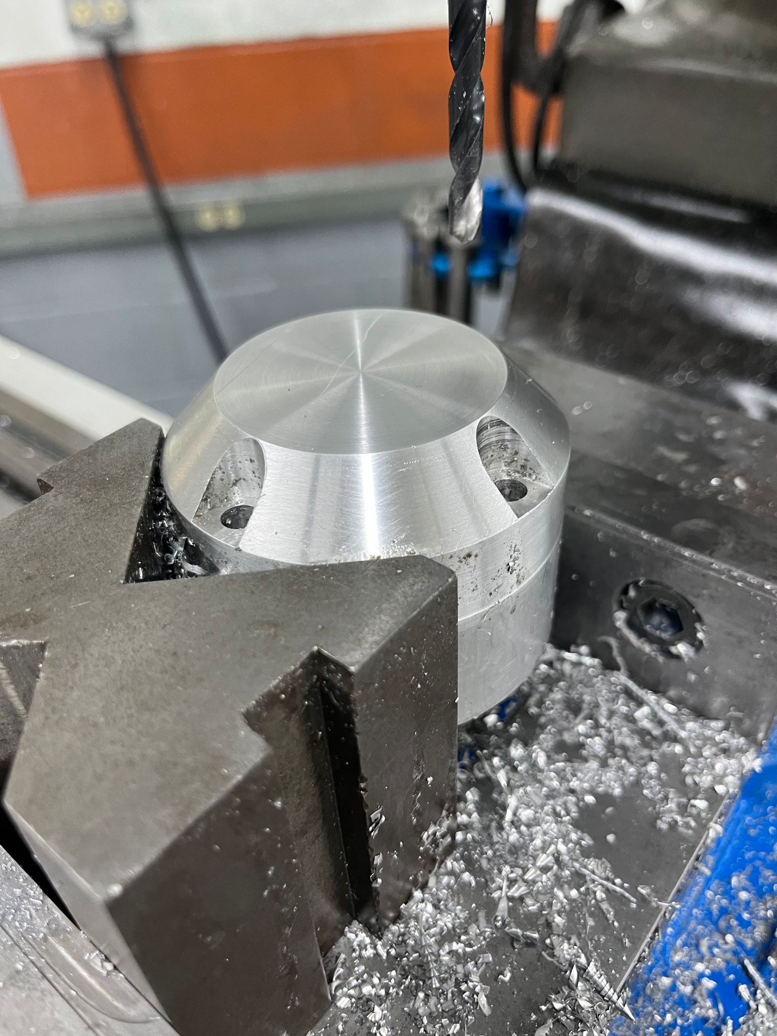
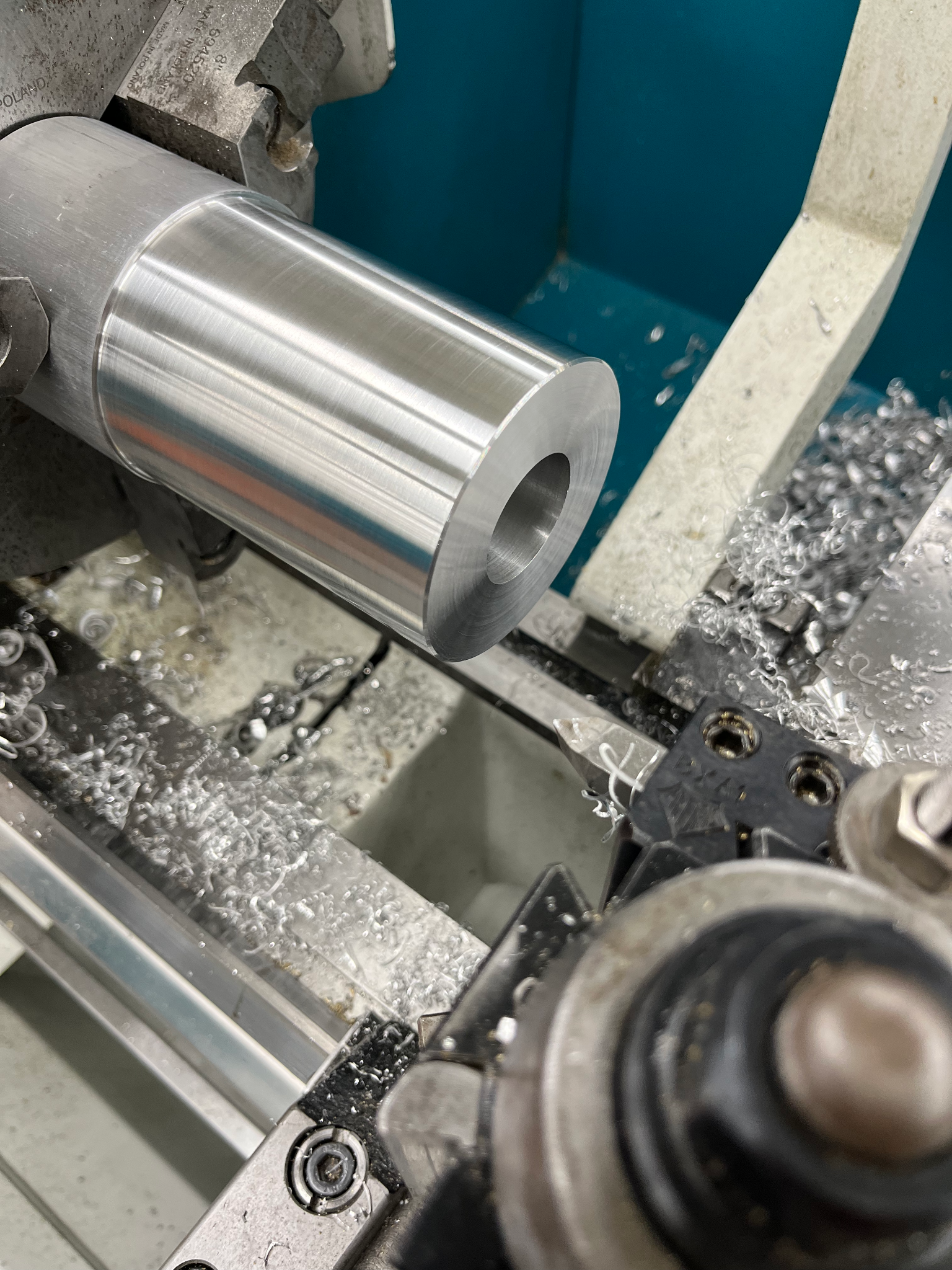
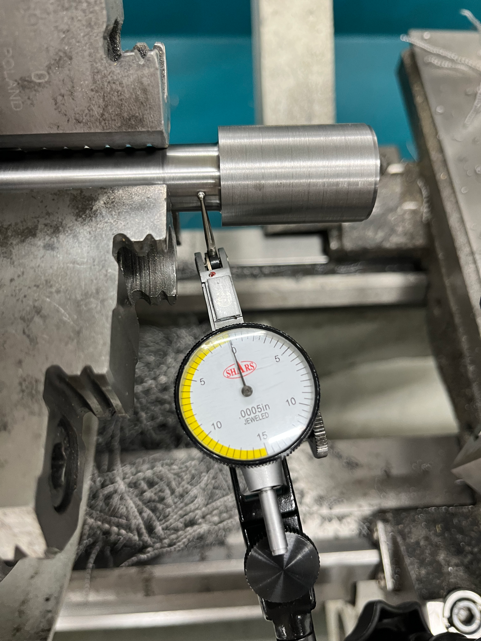
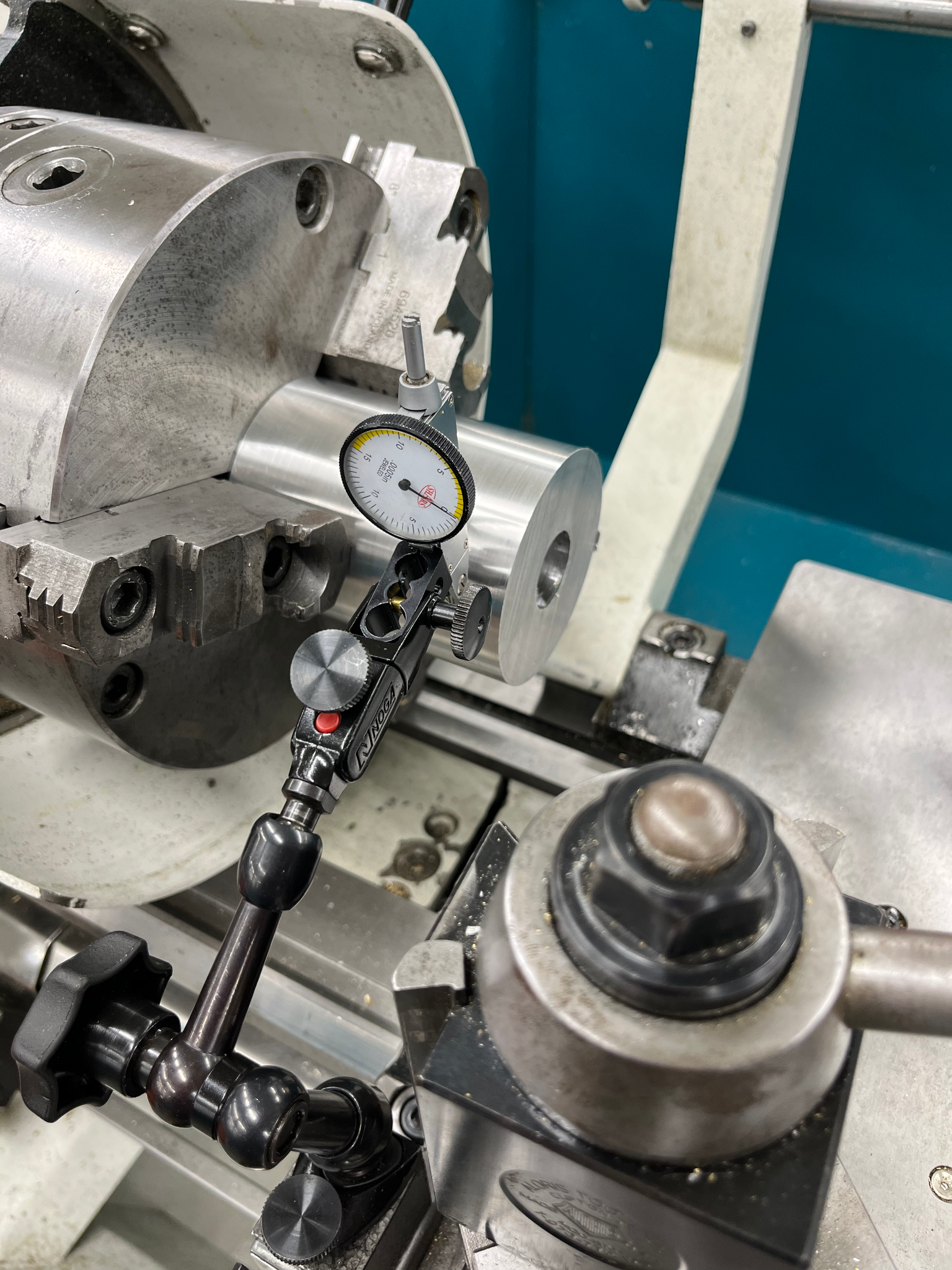
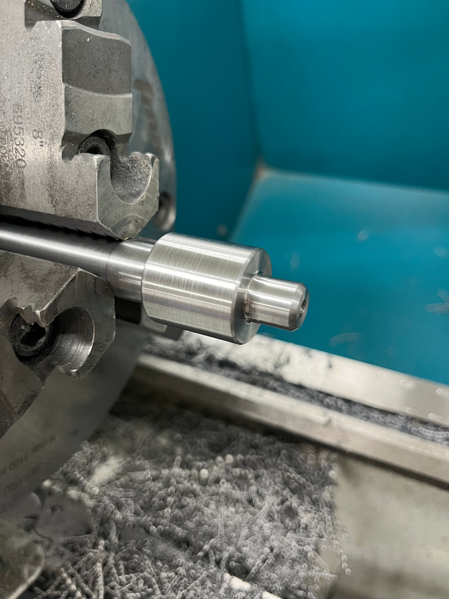

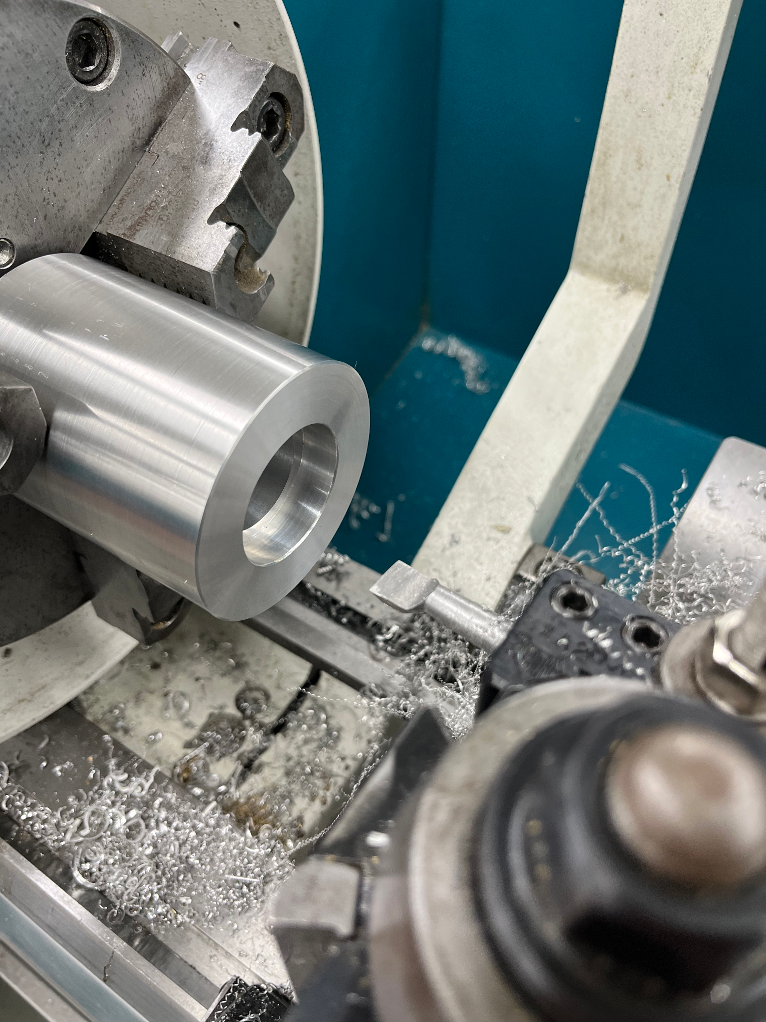
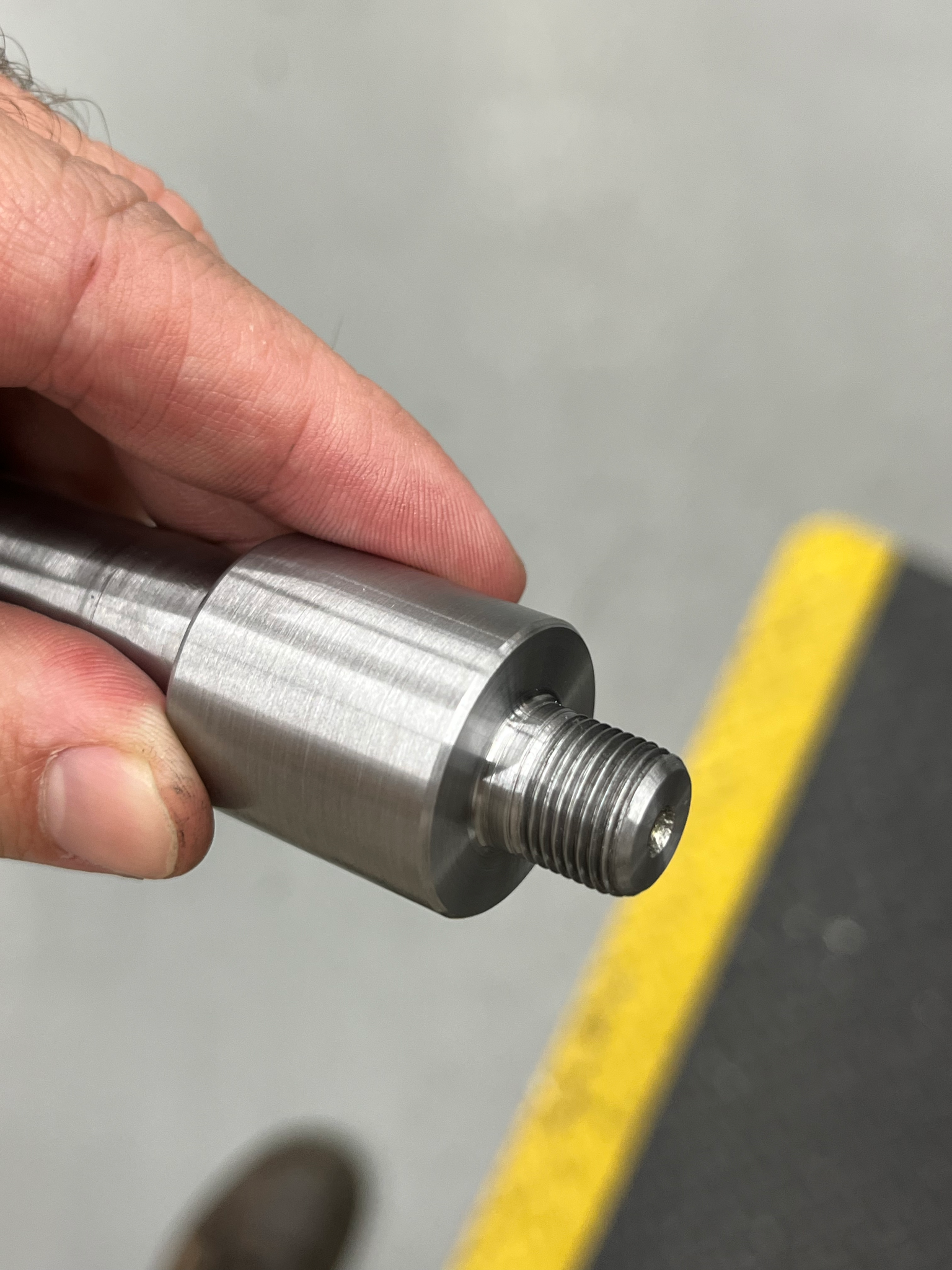
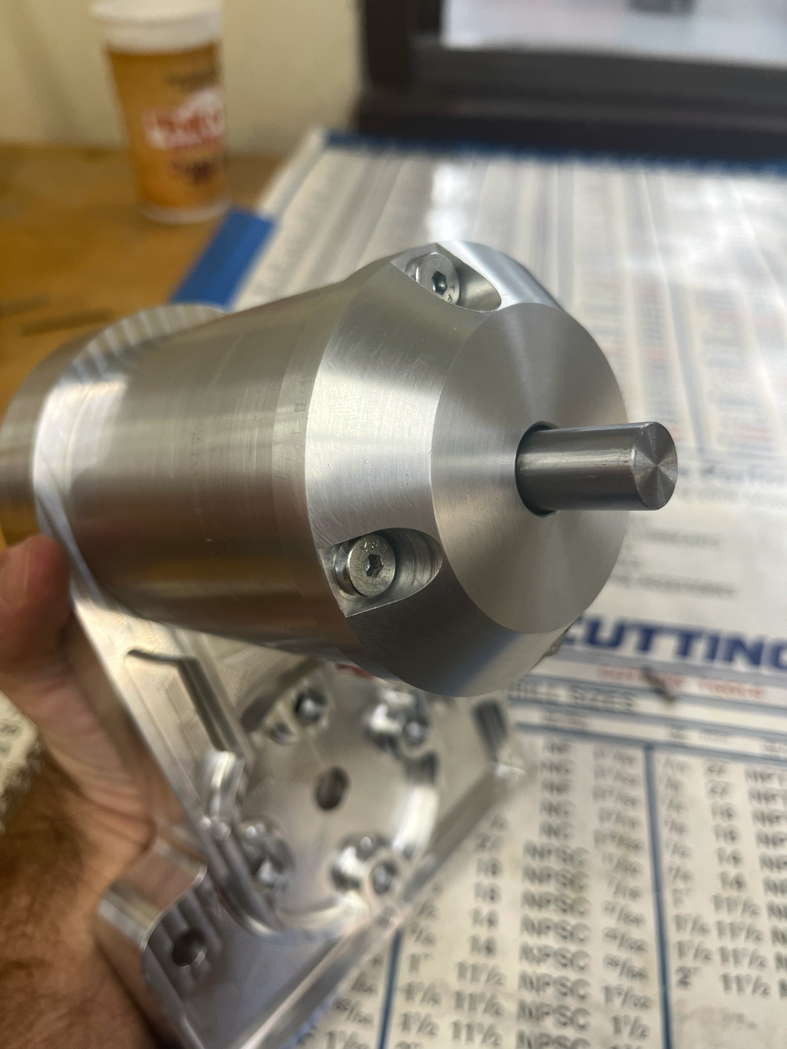
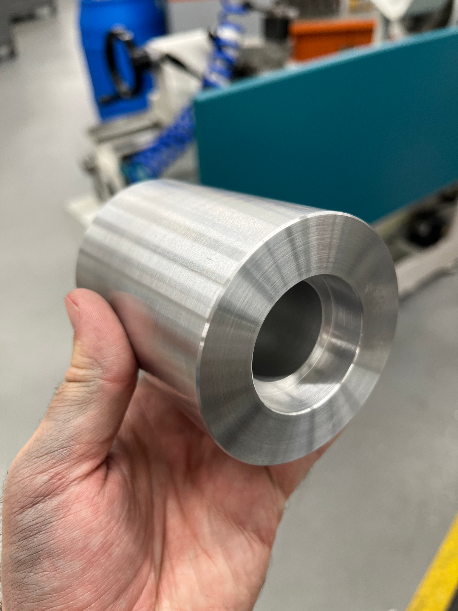
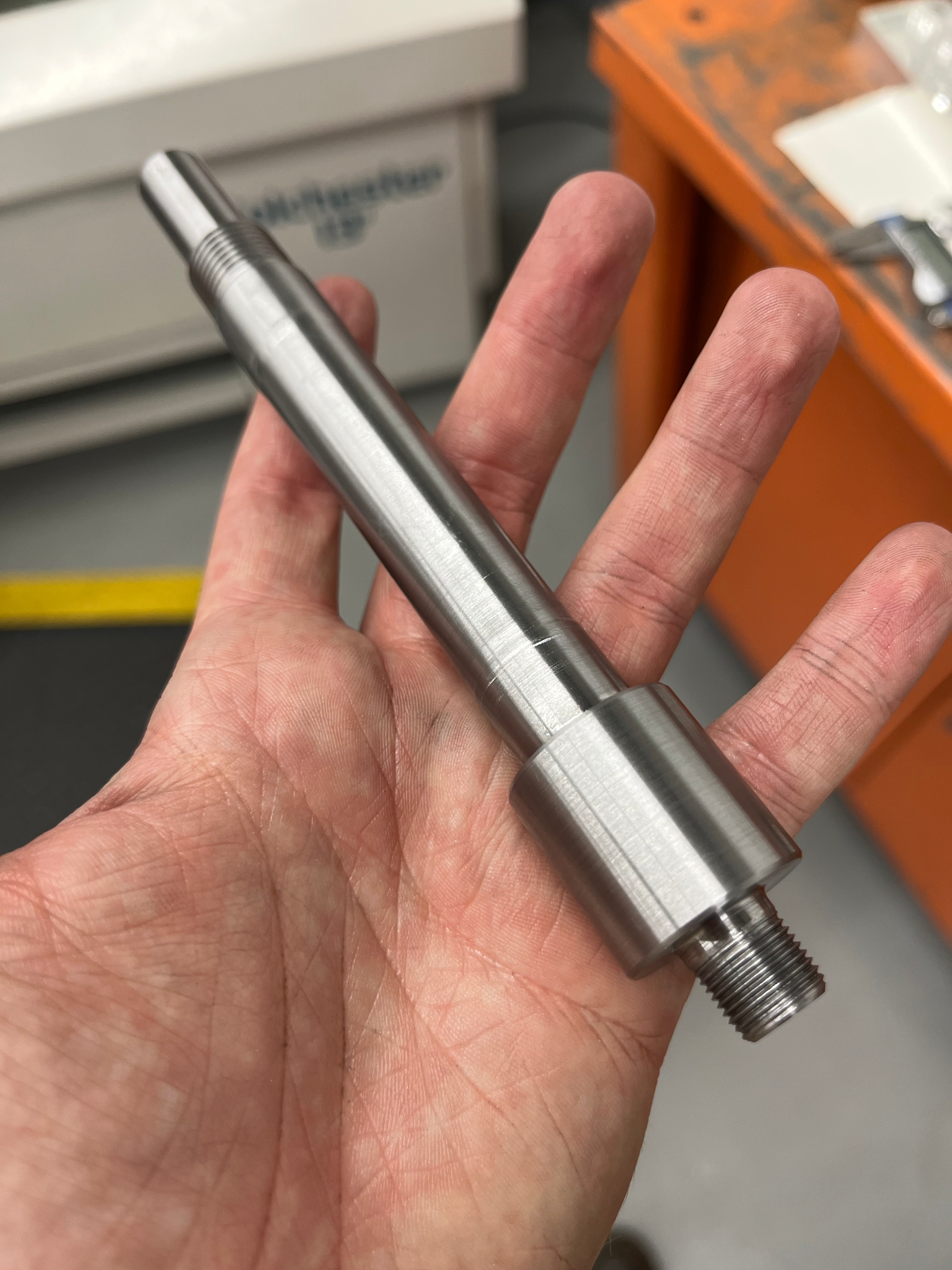
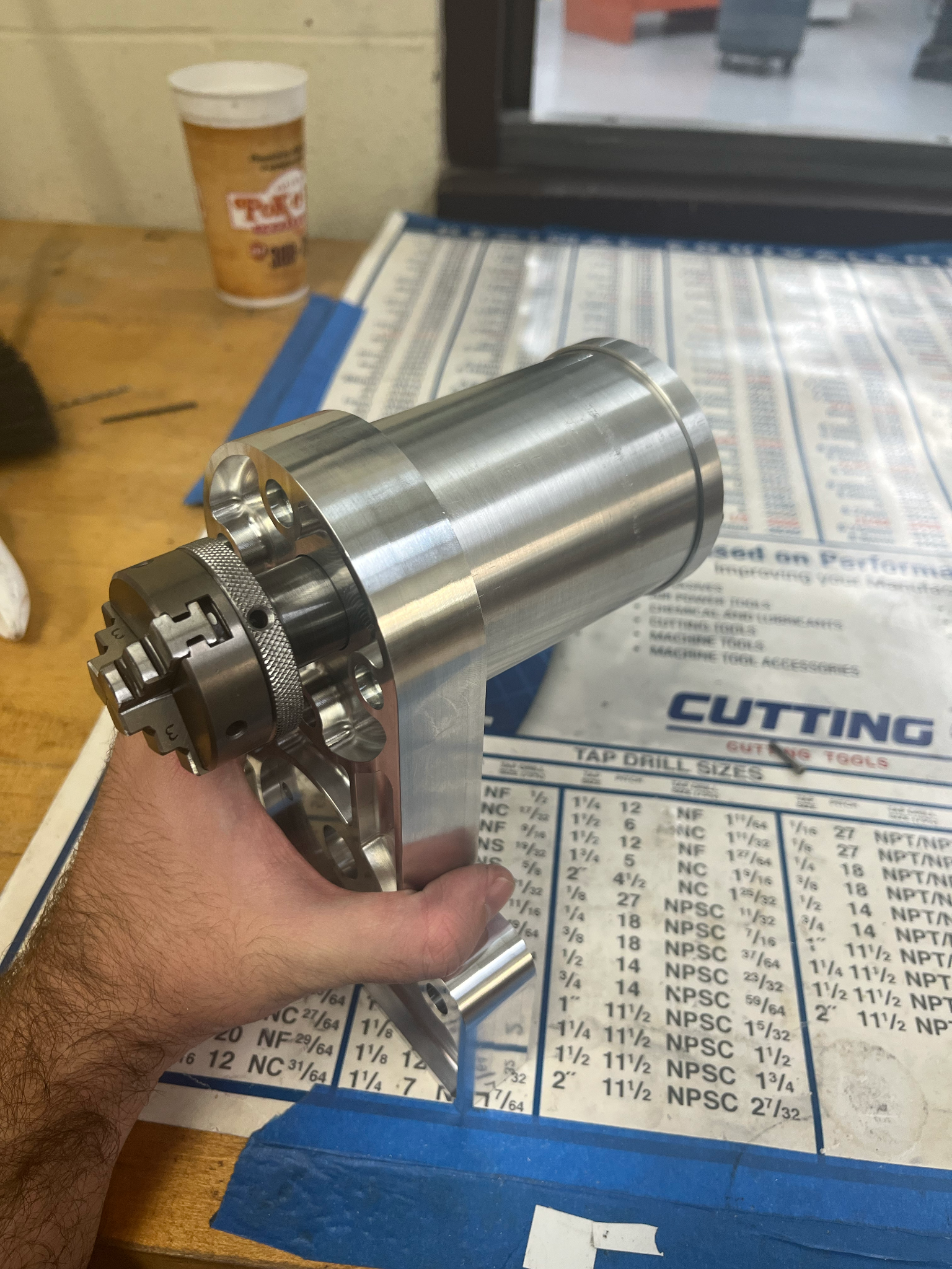
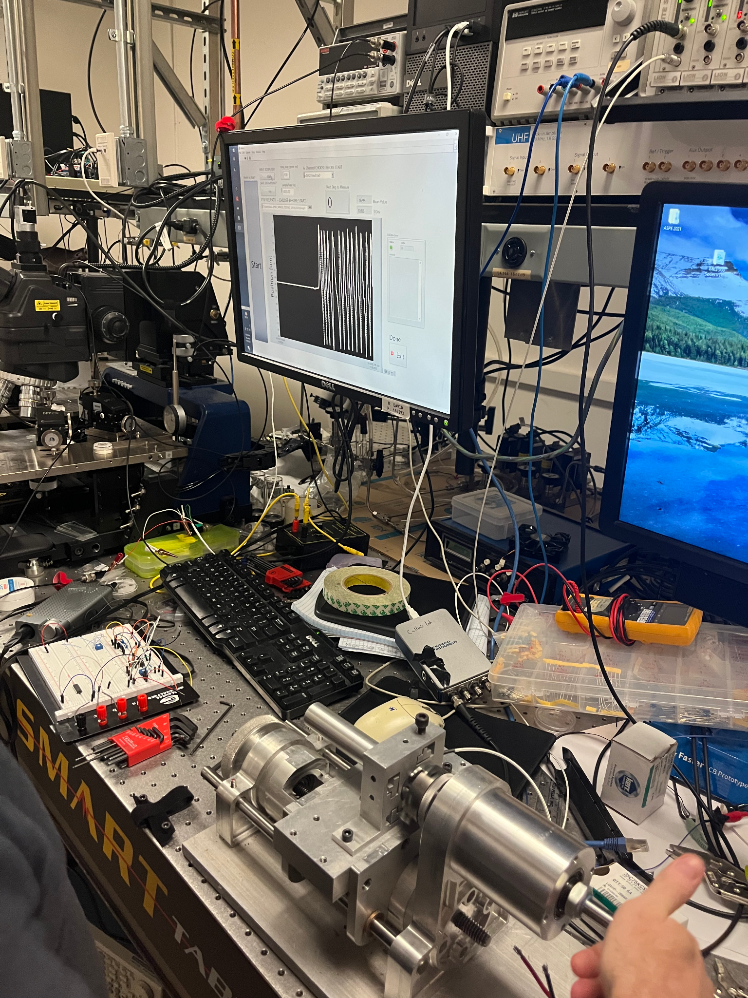
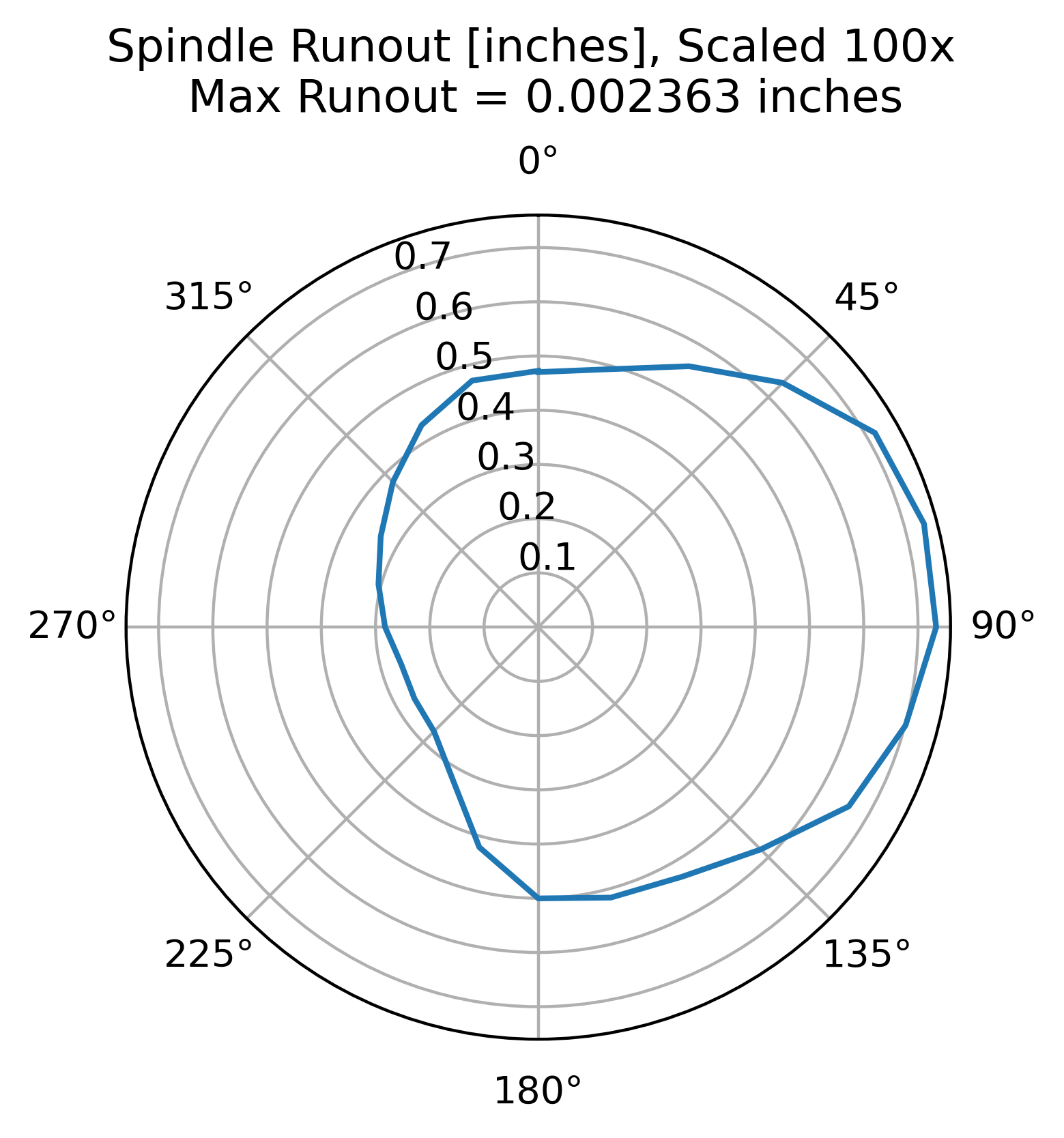
With the spindle complete we could measure the runout which is an important metric to know for lathe performance. If the spindle runout is minimal, you can make concentric features that need multiple fixtures. We used the professor's capacitance probing system to get a very precise runout measurement. Measuring off the workpiece in the chuck, we had a max runout of 2 thousandths of an inch.
Homogeneous Transformation Matrix (HTM) Models
Deriving HTM models is a thorough practice to understand and model complex static systems under loads. If done well, HTMs can predict systematic errors accurately and allow the designer to make changes where it is most needed.
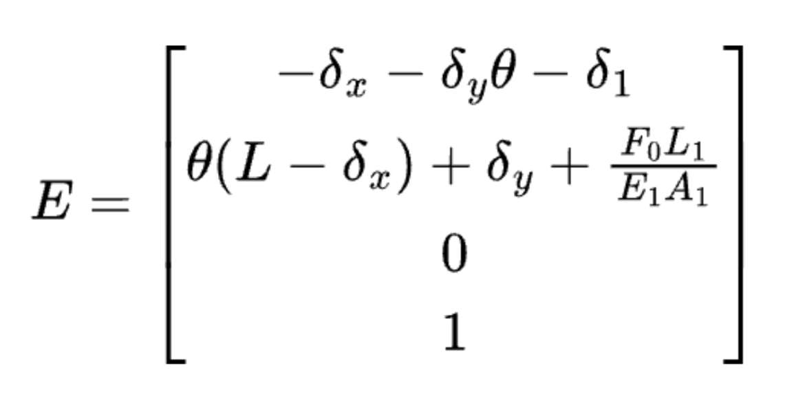
We had to derive two HTMs: one for the chain that runs from the workpiece through the spindle, the headstock, and the base, and one that runs from the tool through the tool holder, the carriage, the rails, and the base.
Drawing clear diagrams of how the structures act and deform under load is important to understanding the system and coming up with the best HTM.
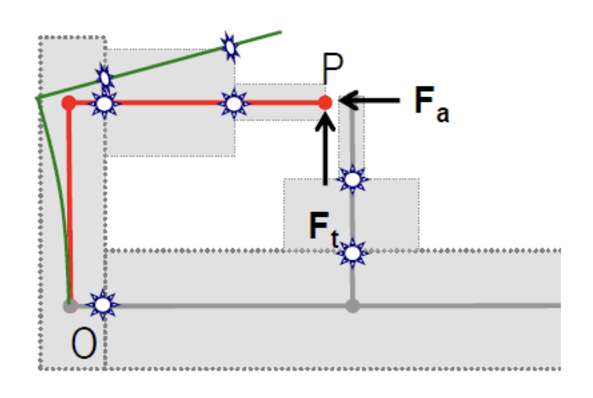
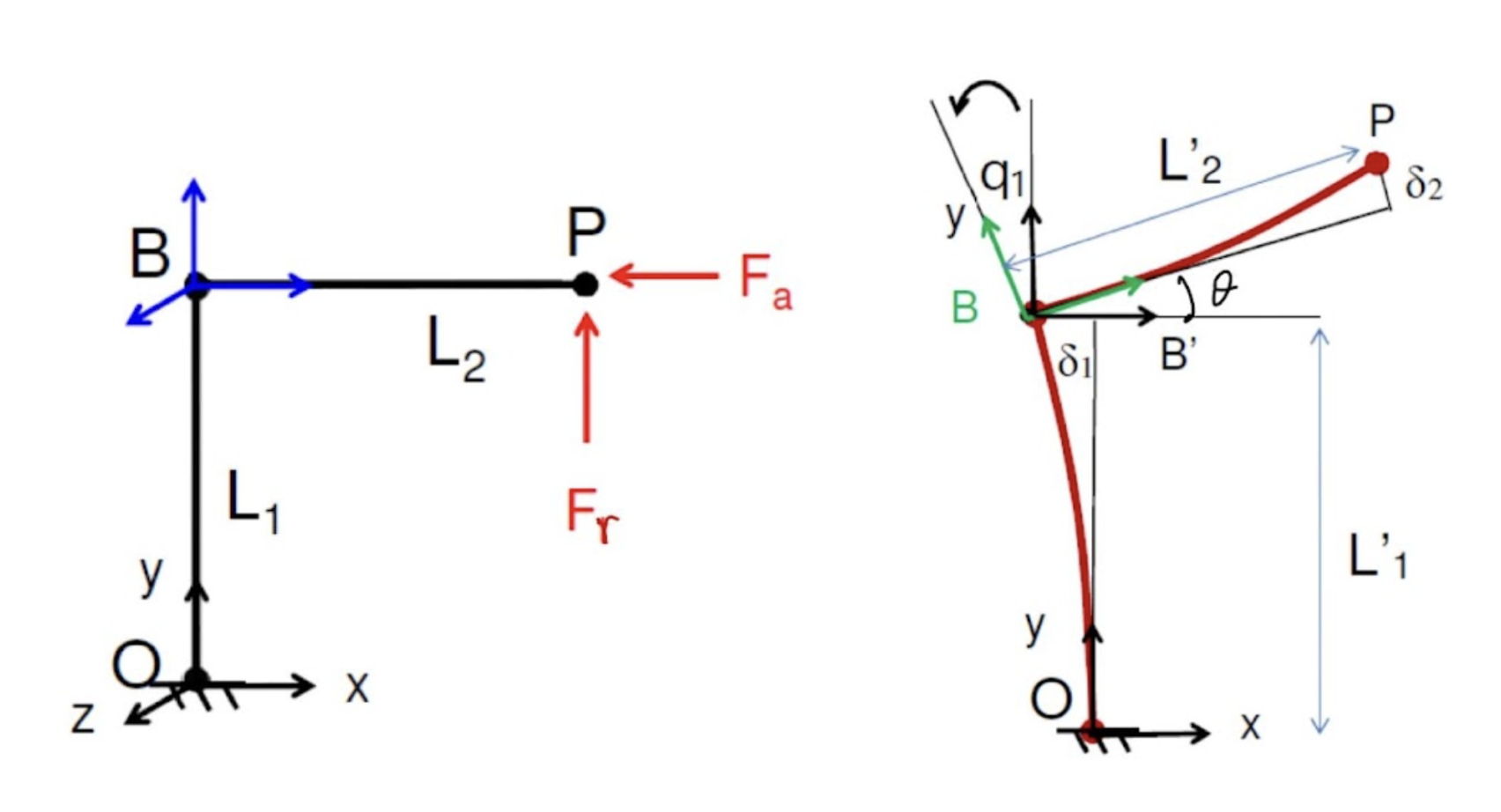
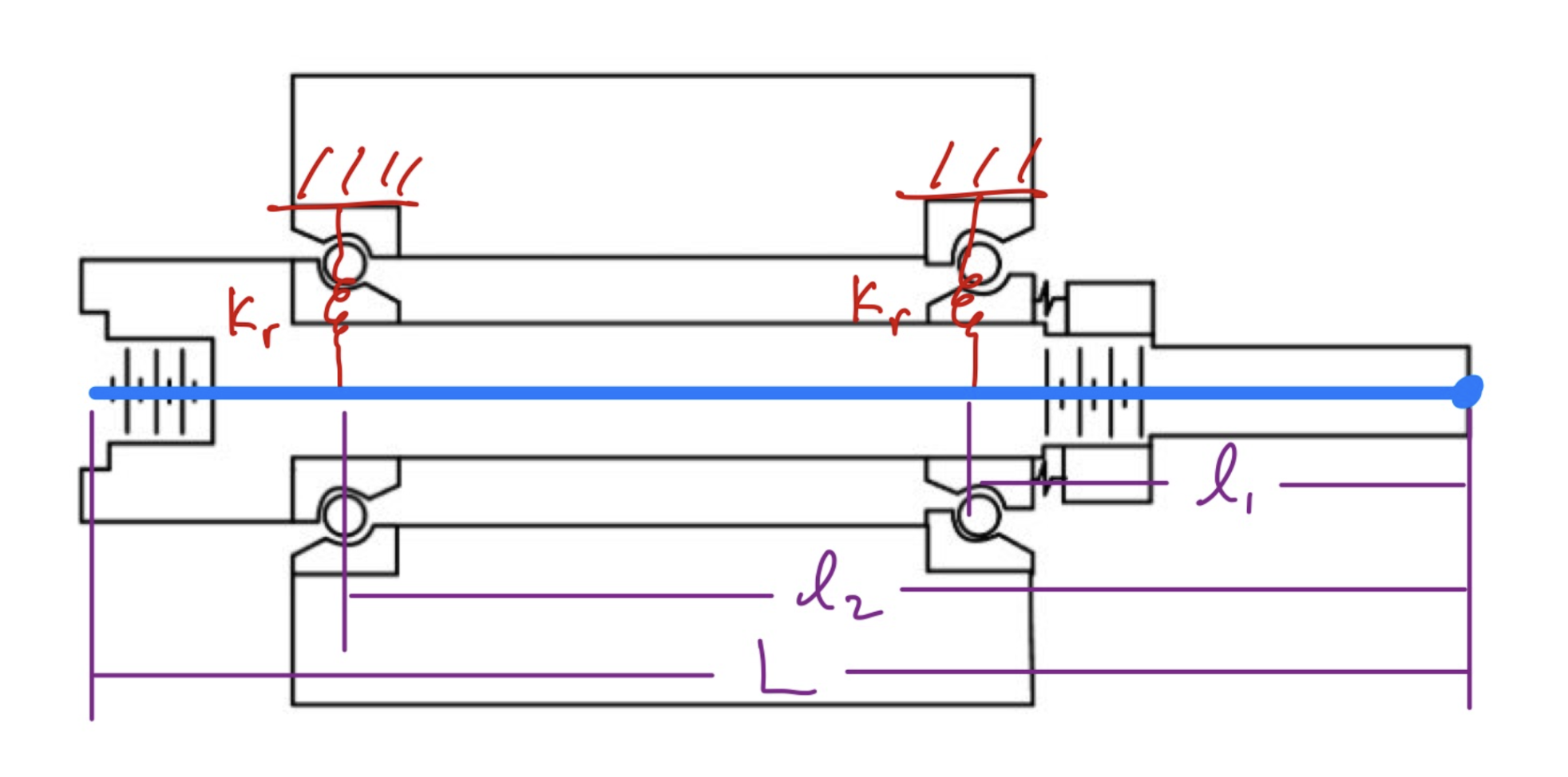
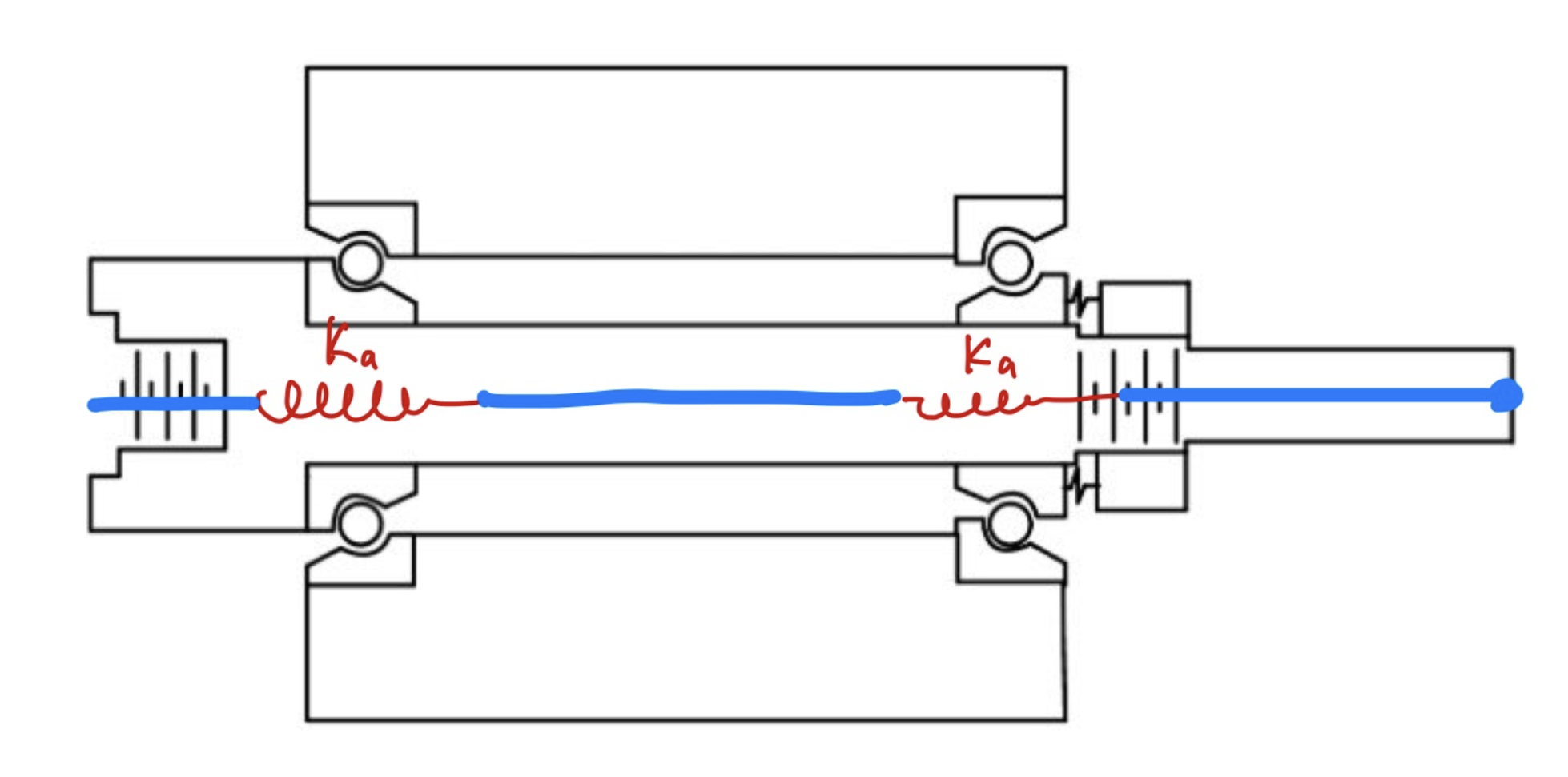
The resulting matrix shows how much positional error the system would have given the cutting forces.
Flexures
In a precision machine, it might seem intuitive to avoid compliance in the system, though some sub-systems in the machine could greatly benefit from compliance if designed correctly. The three flexures we were required to design were the cross-slide, lead-screw nut, and the linear bearing mount.
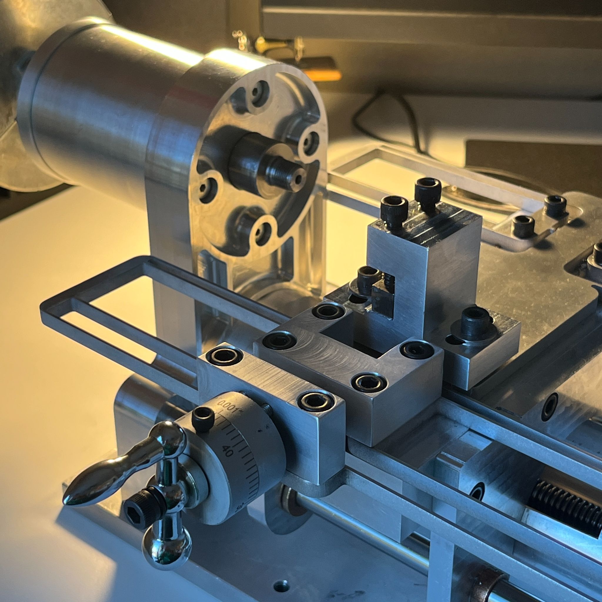
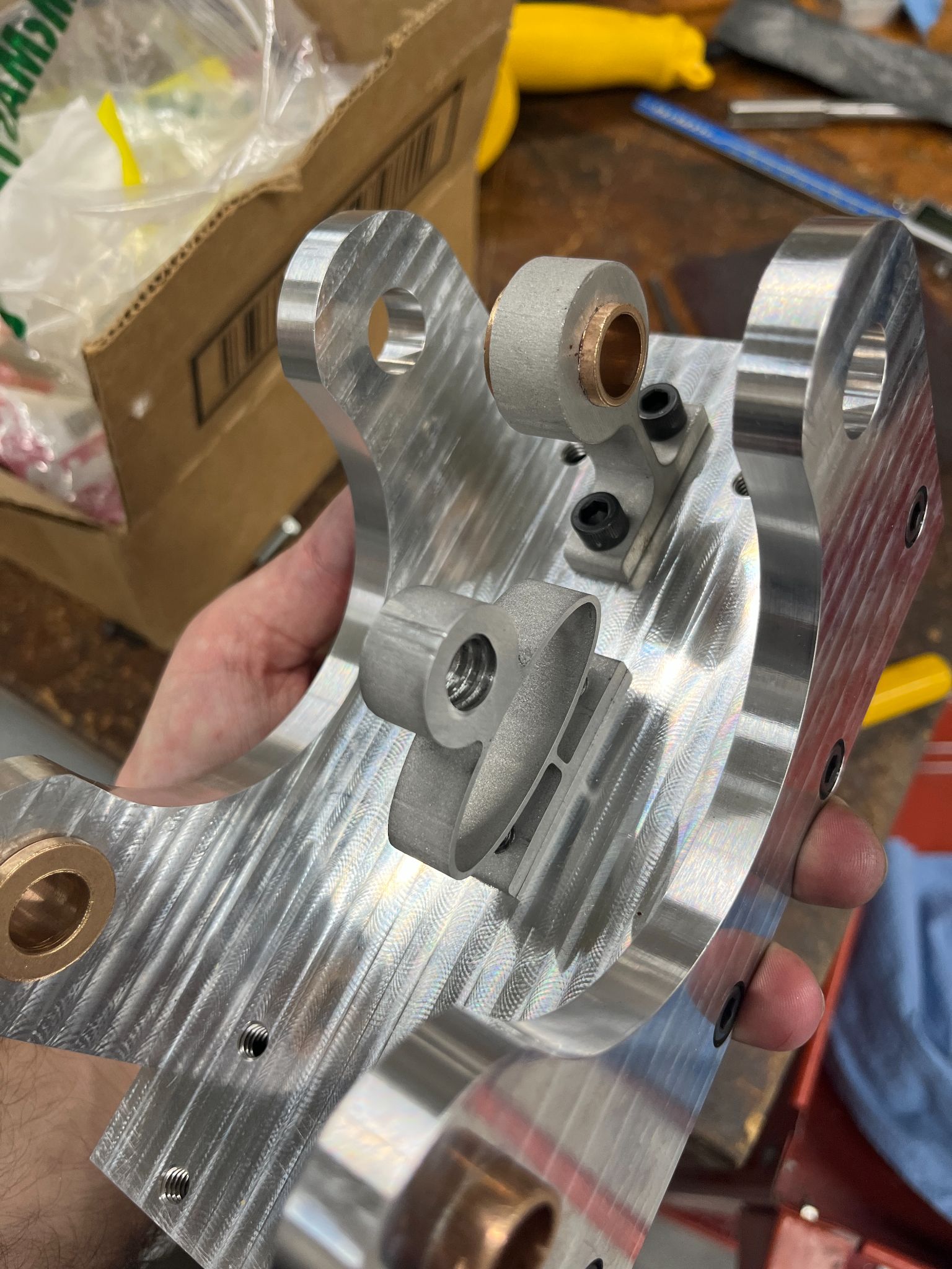
For the cross-slide flexure, we needed to design it such that it would only allow linear movement in one direction and allow for relatively large displacements. This flexure provides the radial travel for the tool holder. Having two linear rail systems one for each axis is not cost effective and creates more issues for assembly and functionality. Since the radial travel component does not need a long travel length, a flexure design is ideal. Also, we designed it in such a way to always place preload on the screw of the hand wheel in the same direction as the cutting force, thus the dial reads the true dimension. The screw feature for the hand wheel was also machined.
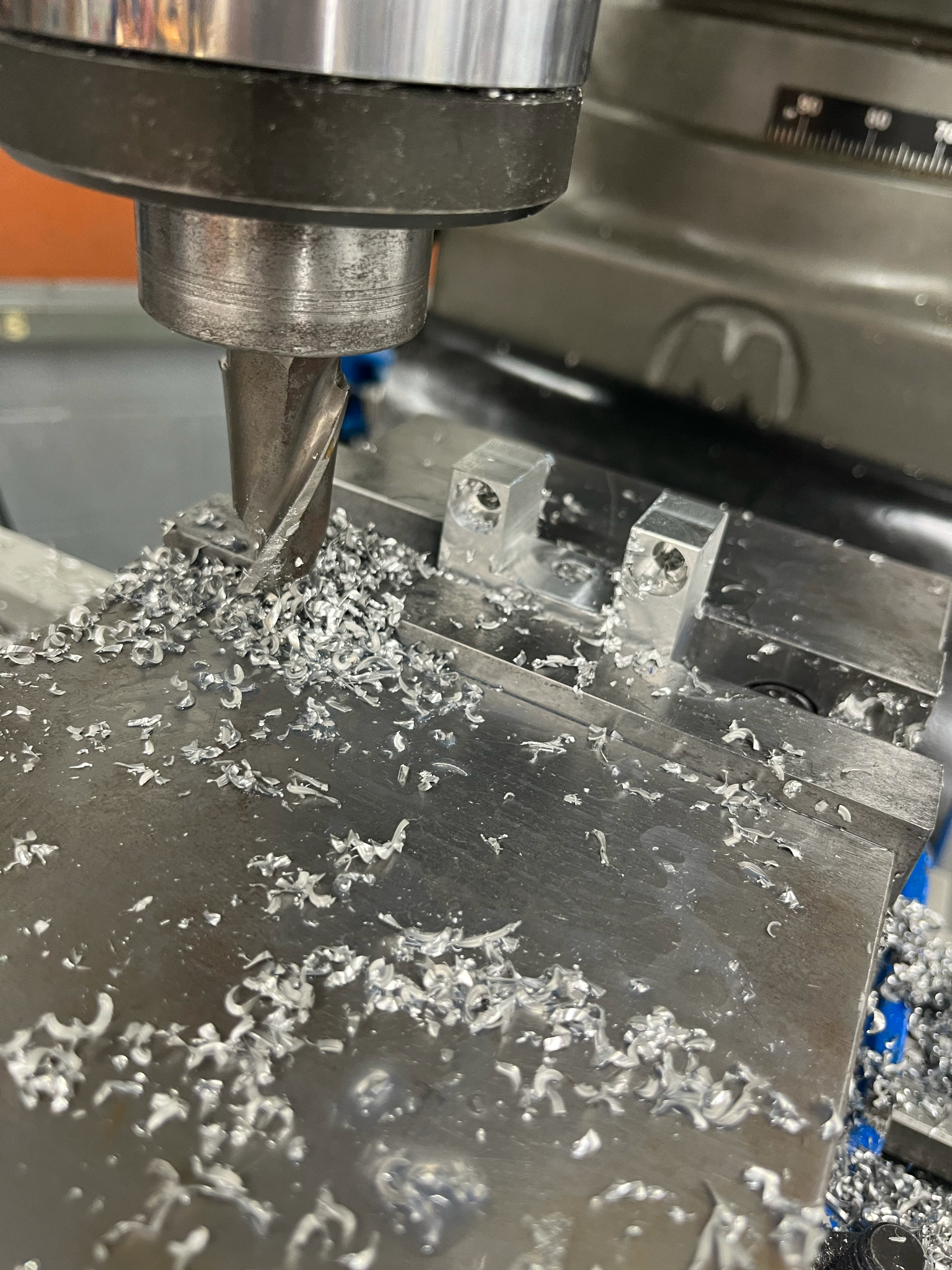
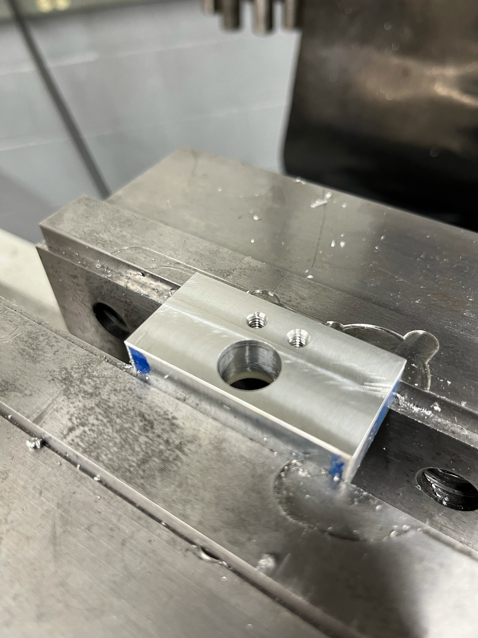
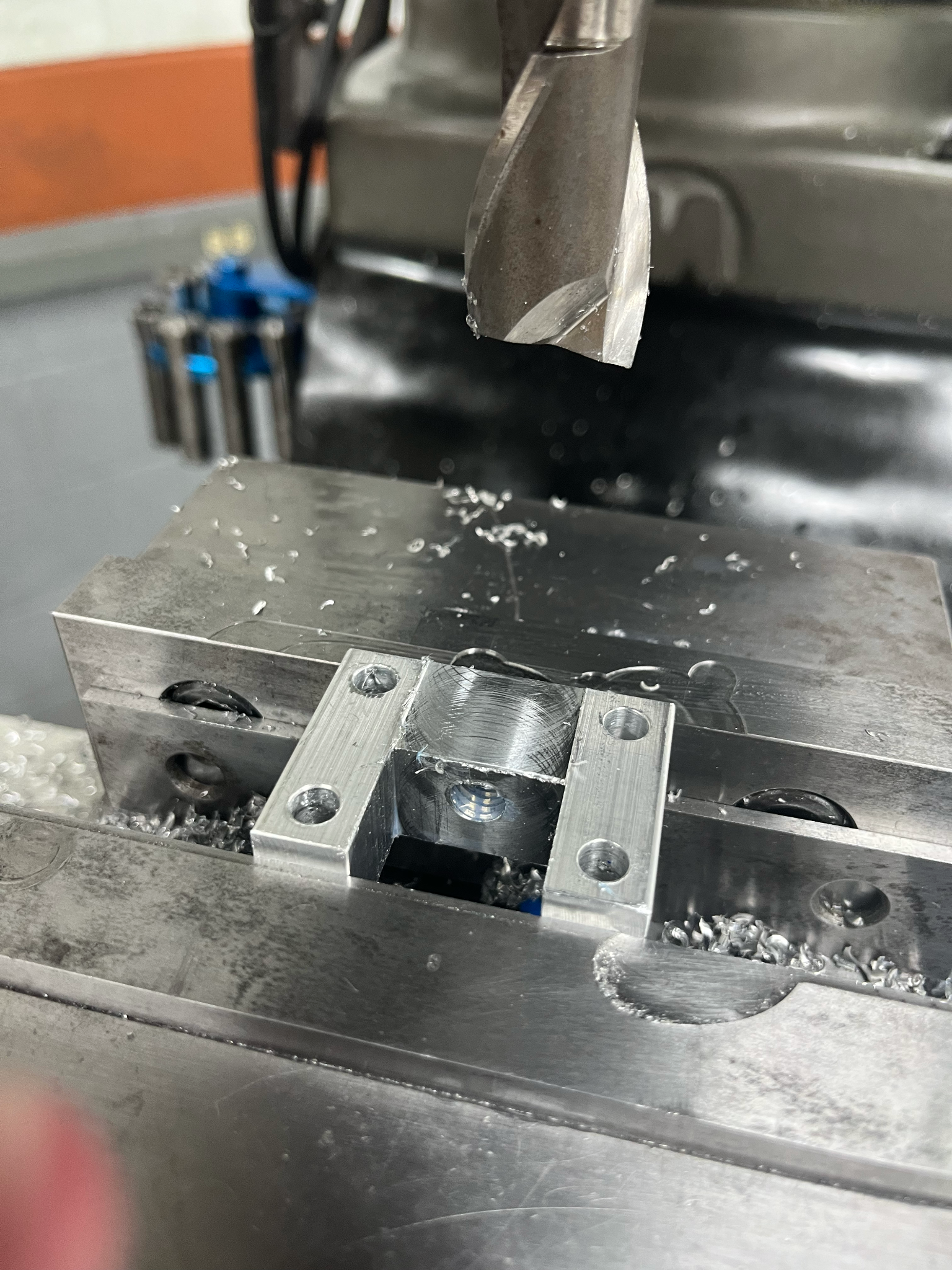
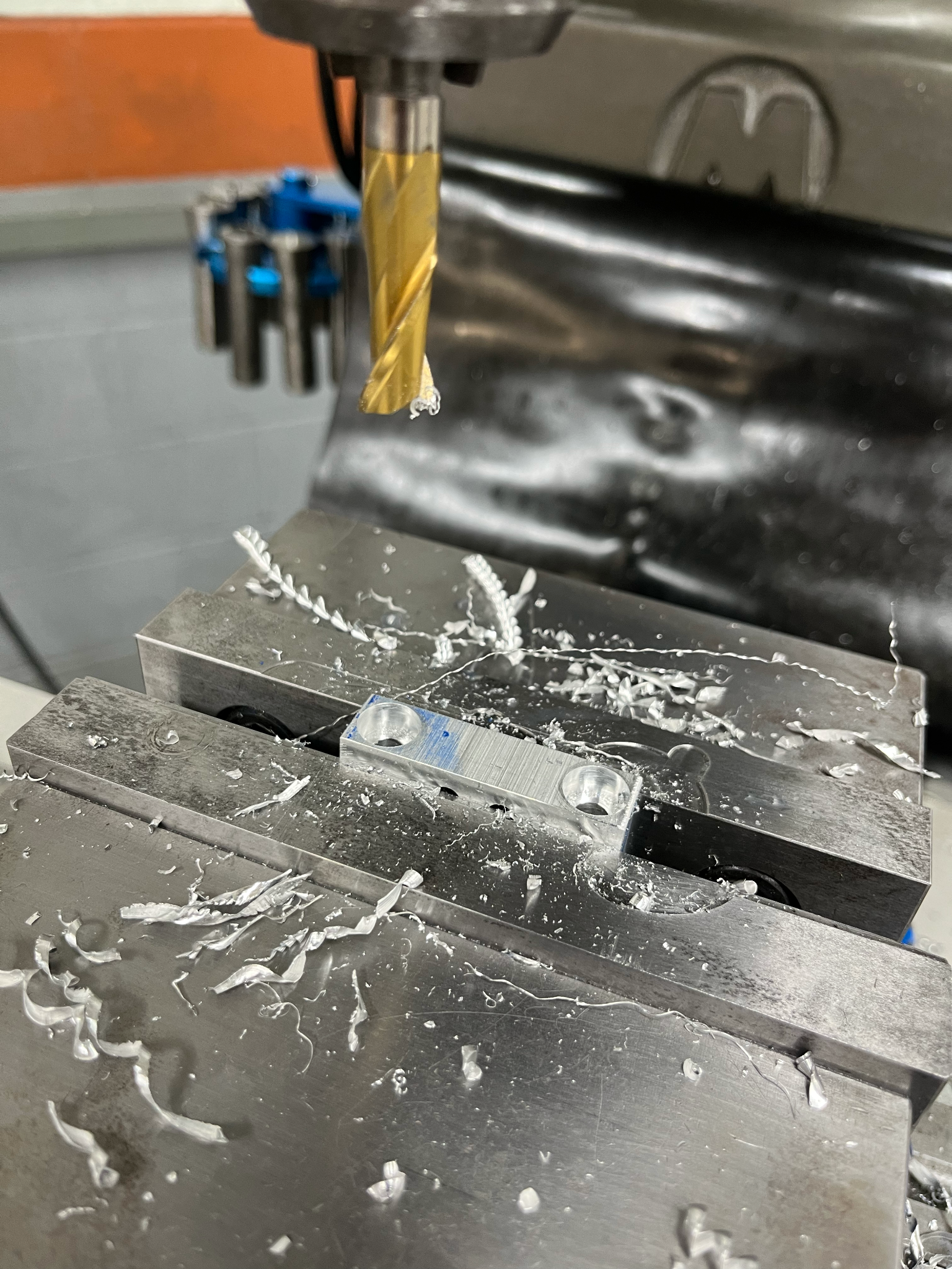
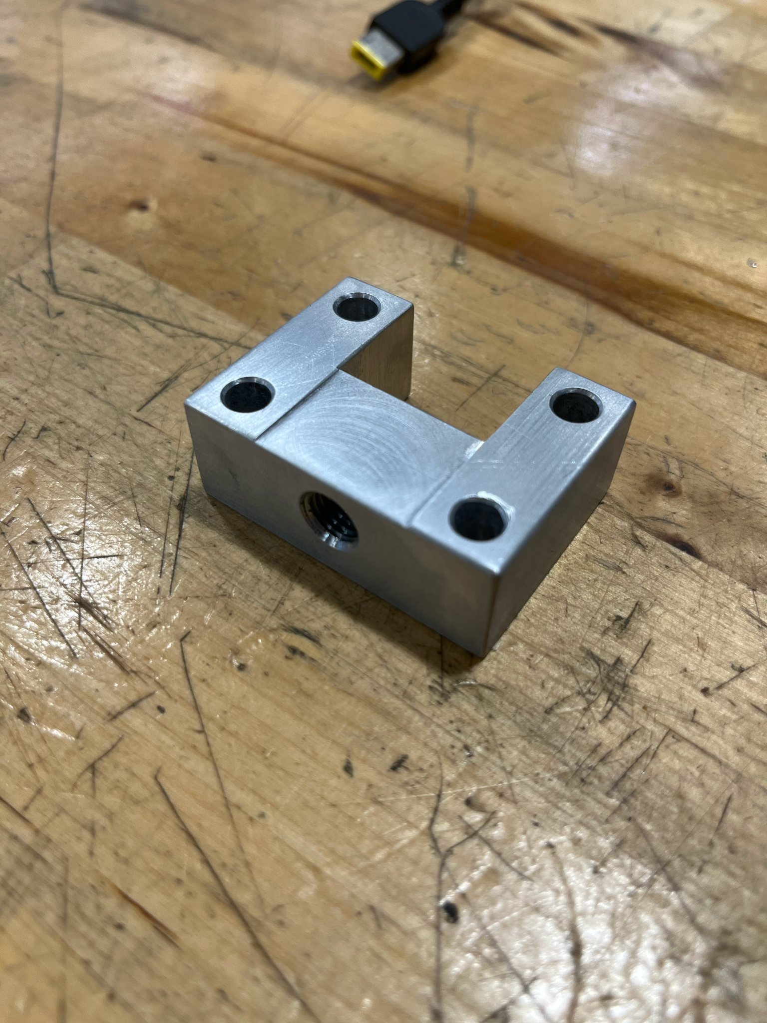
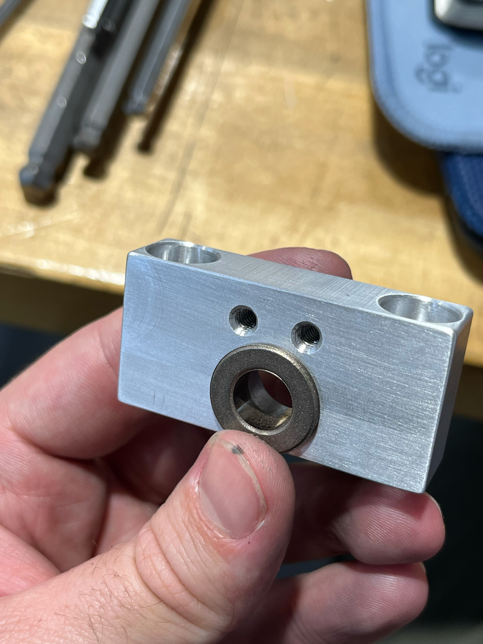
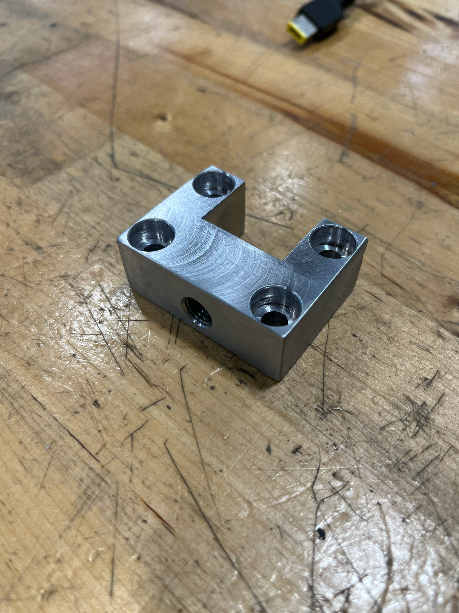
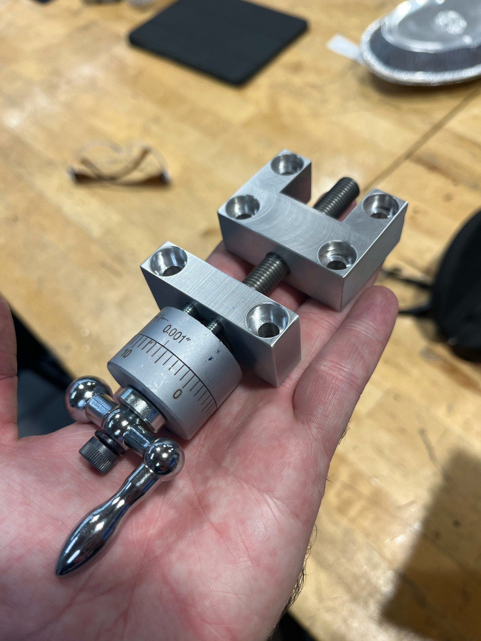
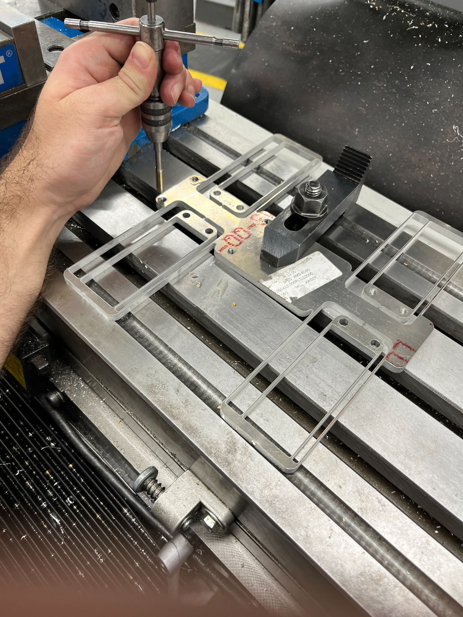
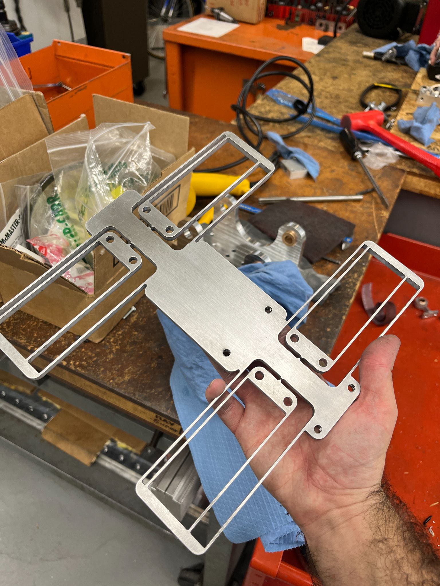
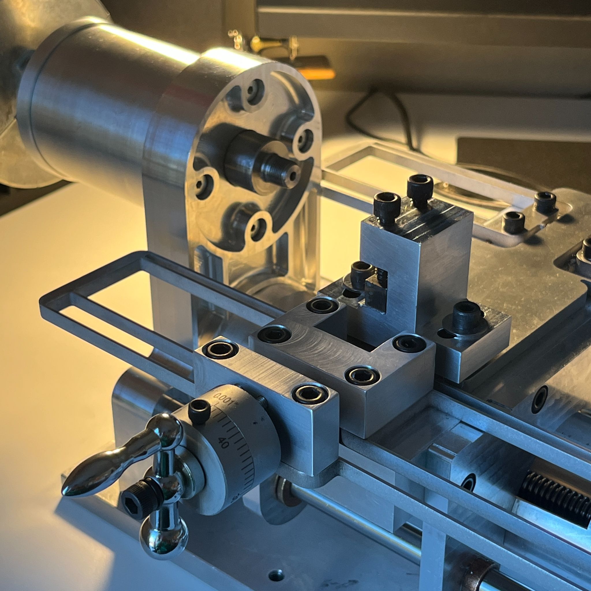
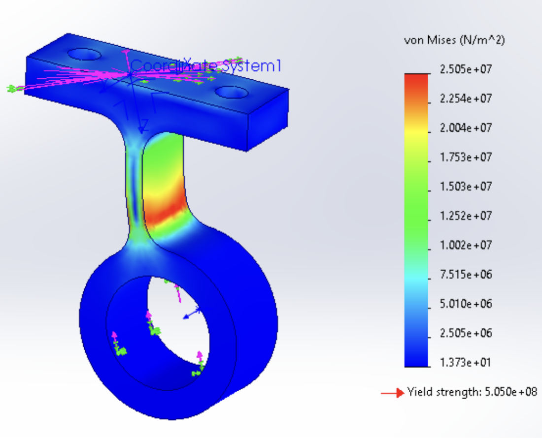
For all of the flexures, we used FEA analysis to ensure that we would have a safety factor of at least three for the given displacements they would experience. Due to the cross-slide flexure's size, we had to also use FEA analysis for frequency analysis, checking that the speed we would be running our lathe did not match the modal resonance values estimated.
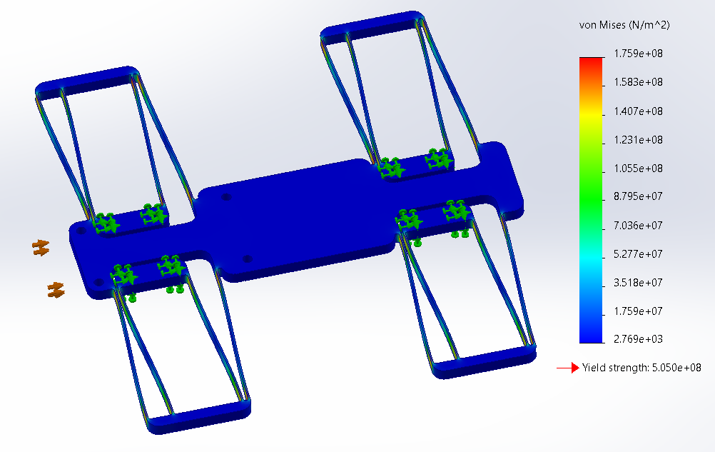
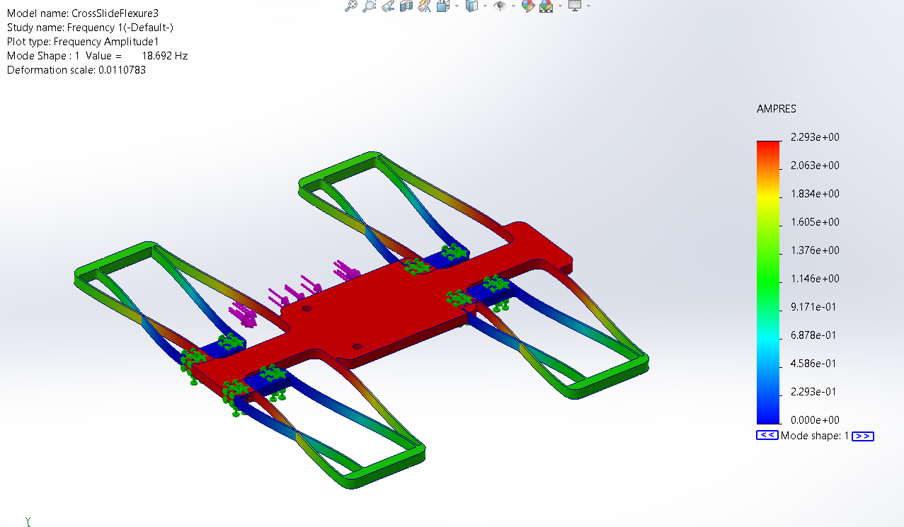
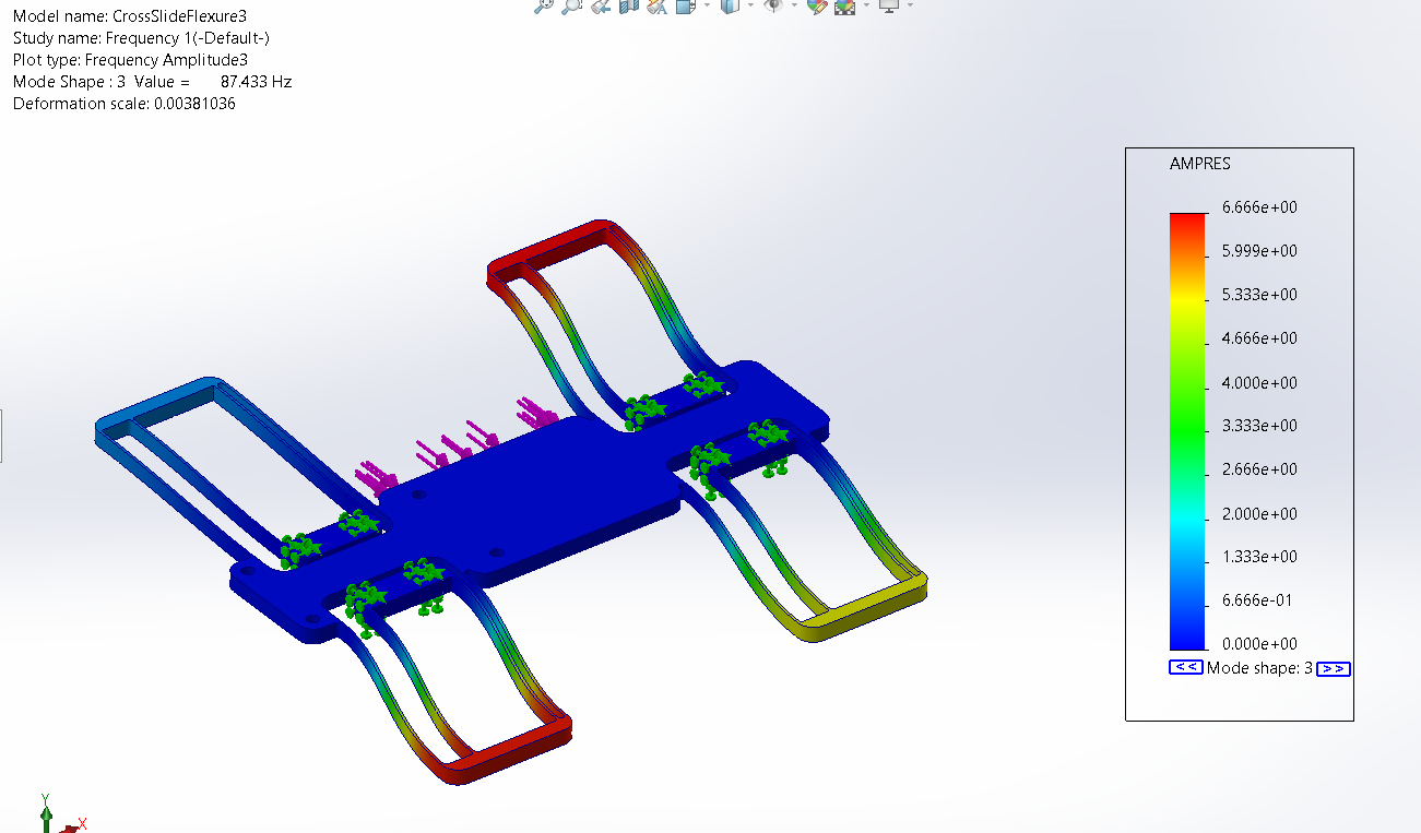
For the lead-screw nut flexure, we needed to design it in a way such that it is very stiff in all directions except for in one plane of translational movement. The flexibility in this plane is needed because cheap lead screws are never perfectly straight.

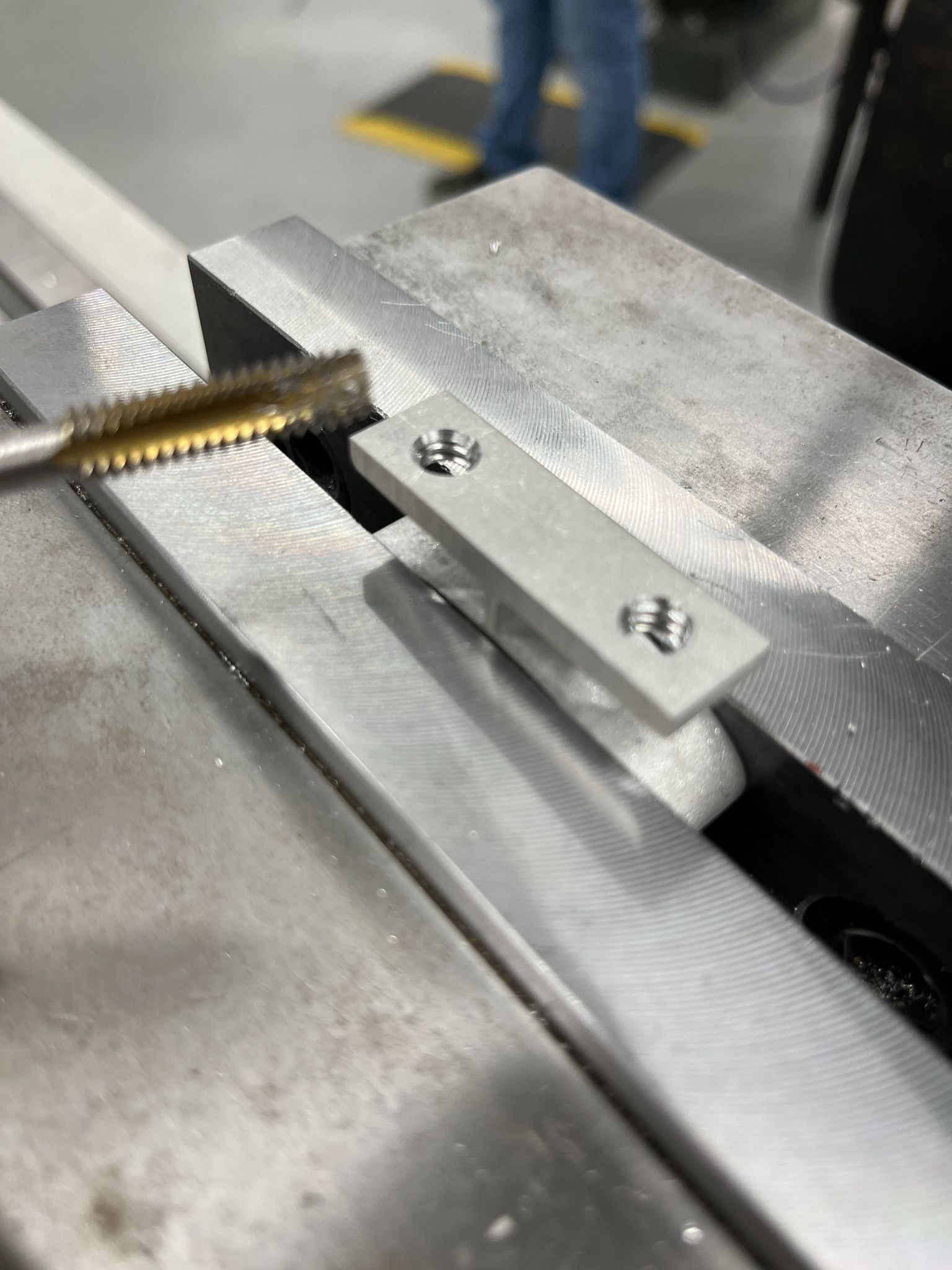
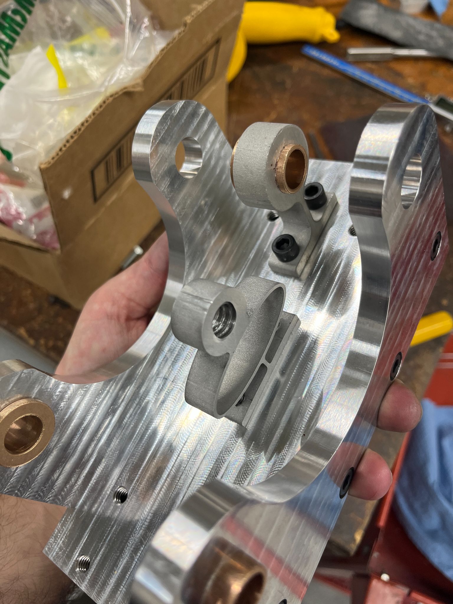
The linear bearing nut is the simplest of the three. It only allows for lateral movement and twisting. Without this flexure, if the two rails are not parallel then the carriage would eventually bind.
Belt and Pulley Selection
Through cutting tests on the school's lathes we found that a speed of 900 rpm felt the best for cutting the aluminum. Since the AC motor could only run at around 1800 rpm we chose a 2:1 pulley ratio for reducing the speed. We chose a V-belt and pulleys because they can handle high torques and high speeds, and they are cheap. We did hand calculations to figure out the necessary pretension and distance between the pulleys.
Post-Processing
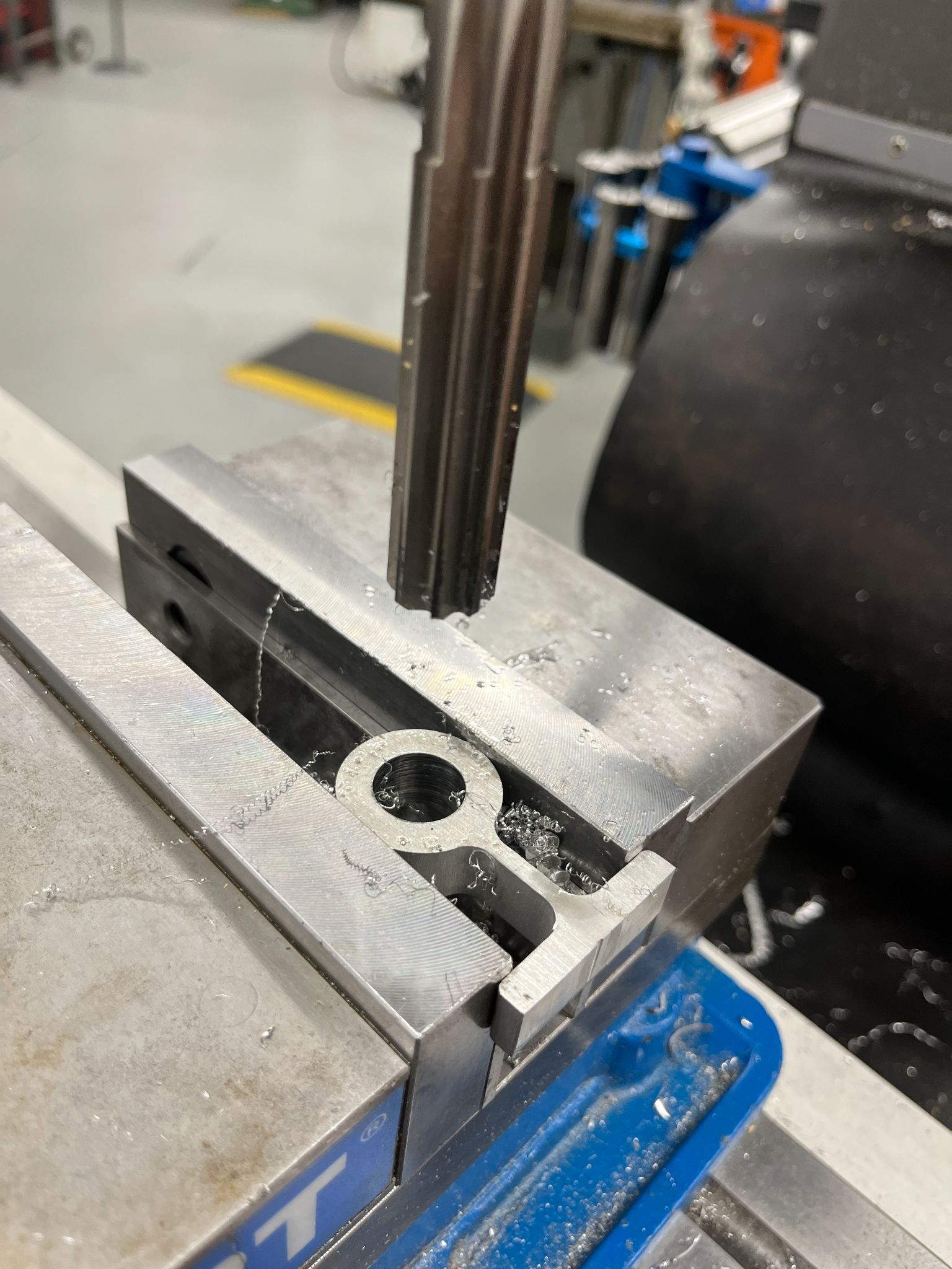
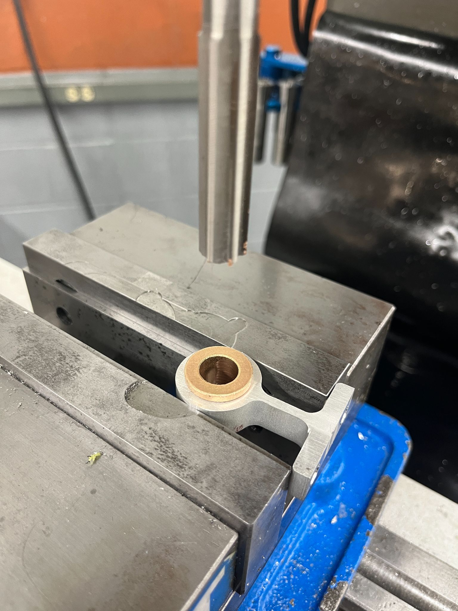
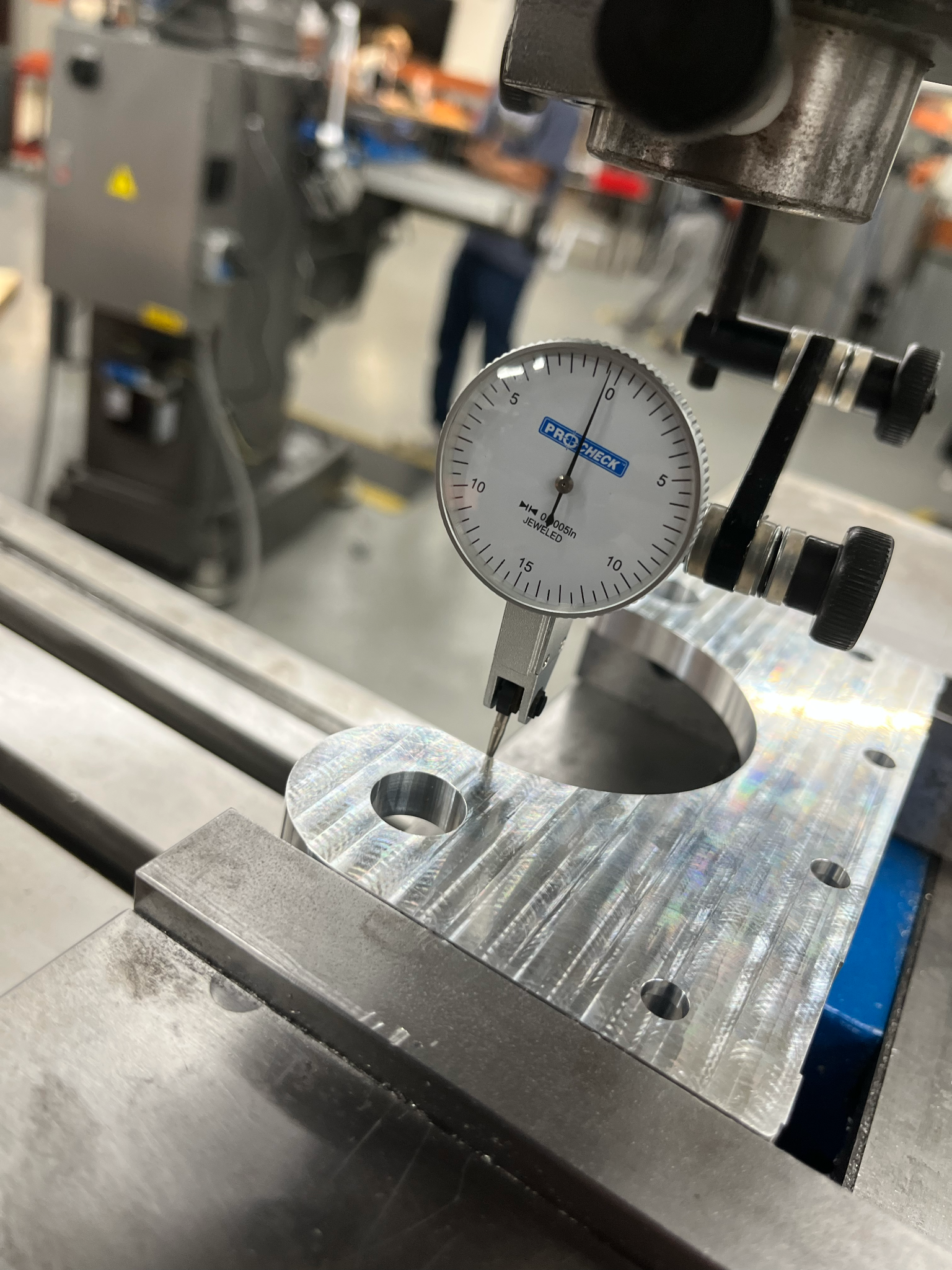
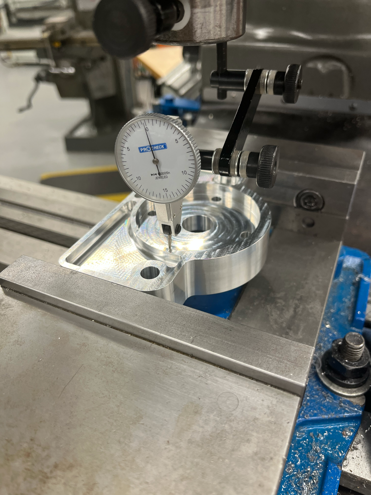
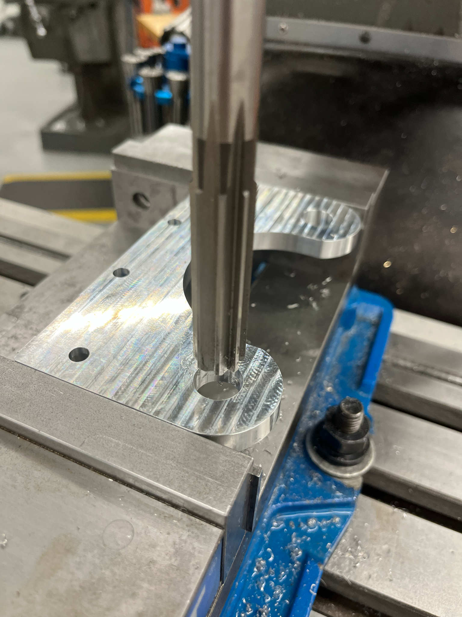
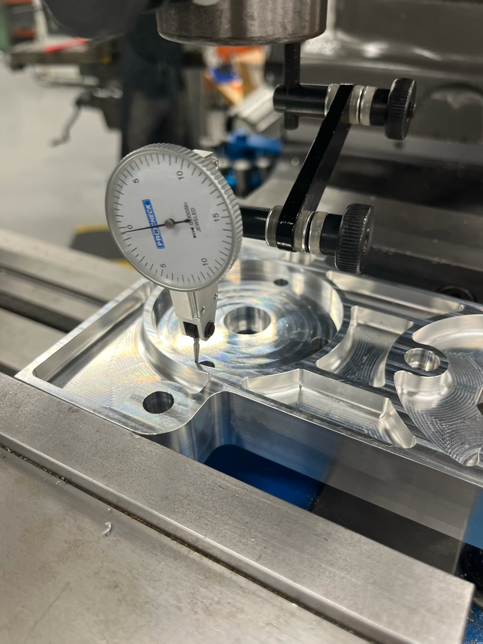
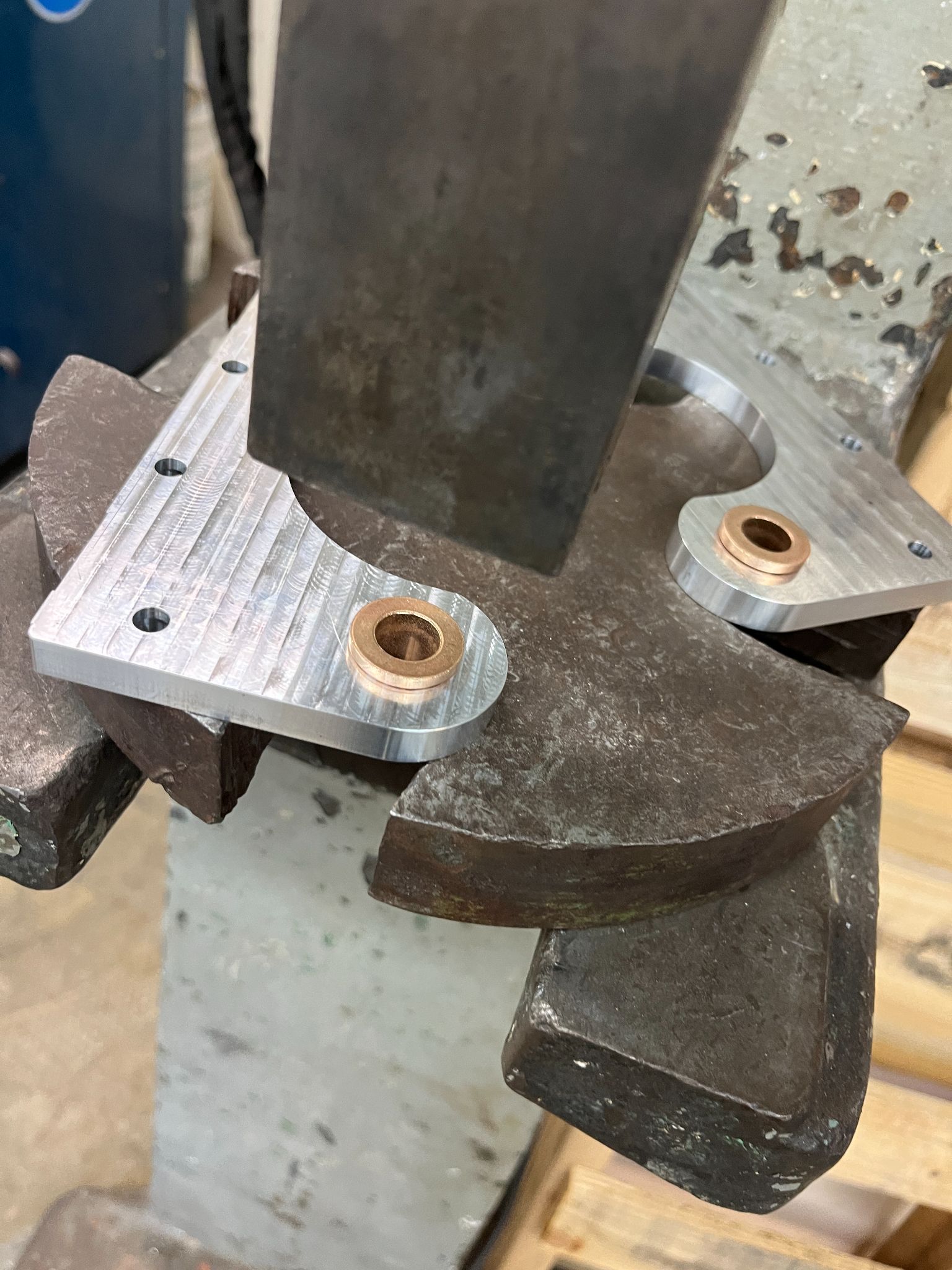
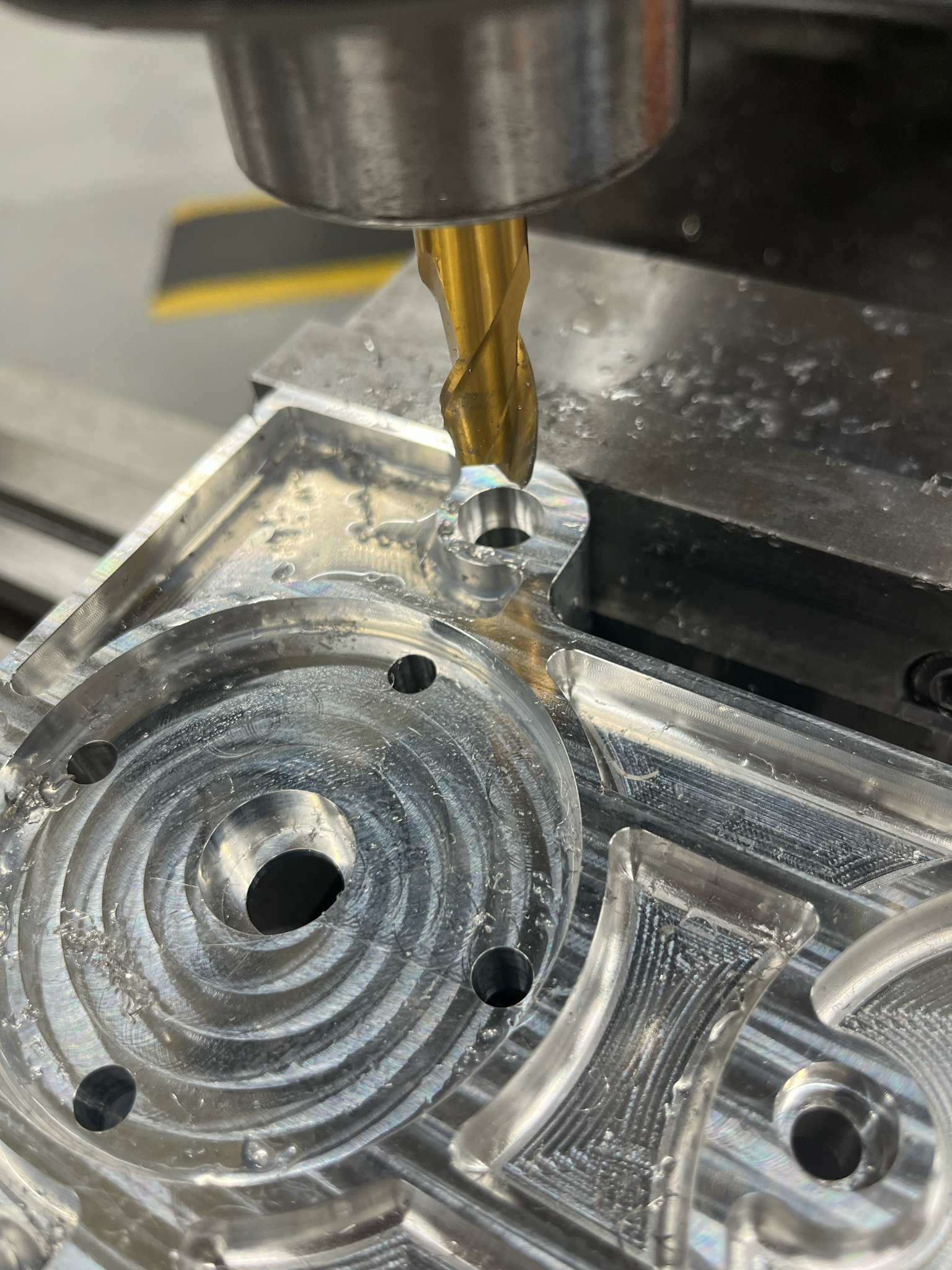
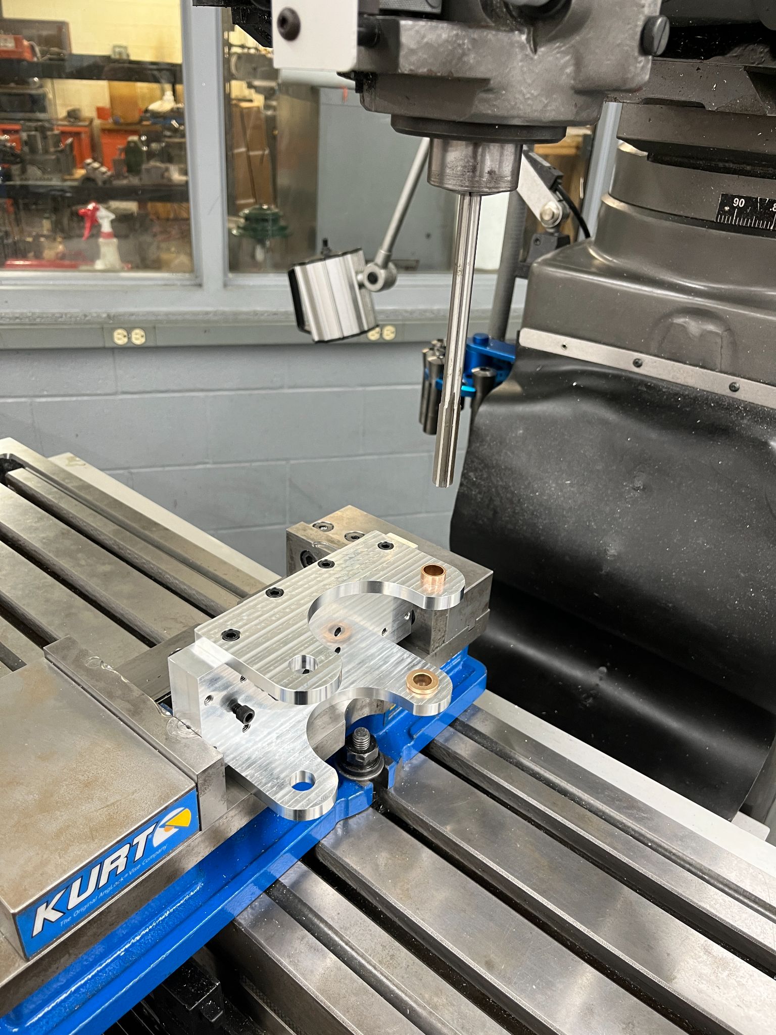
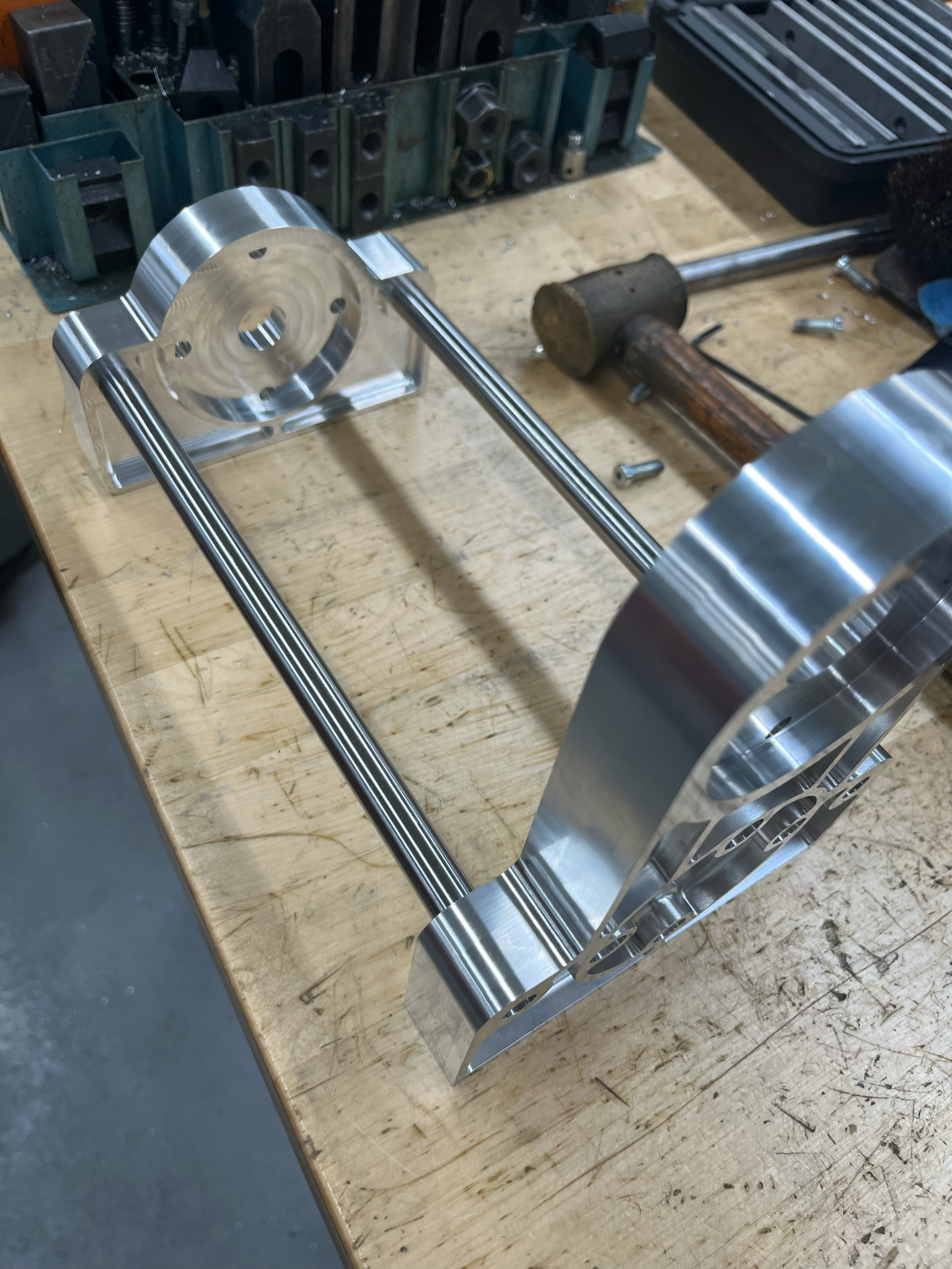
Most of the parts were machined for us but required us to make alterations to work with our design choices. These post-processing operations included a lot of dial indicating, turning down diameters, and boring holes.
One Last Touch
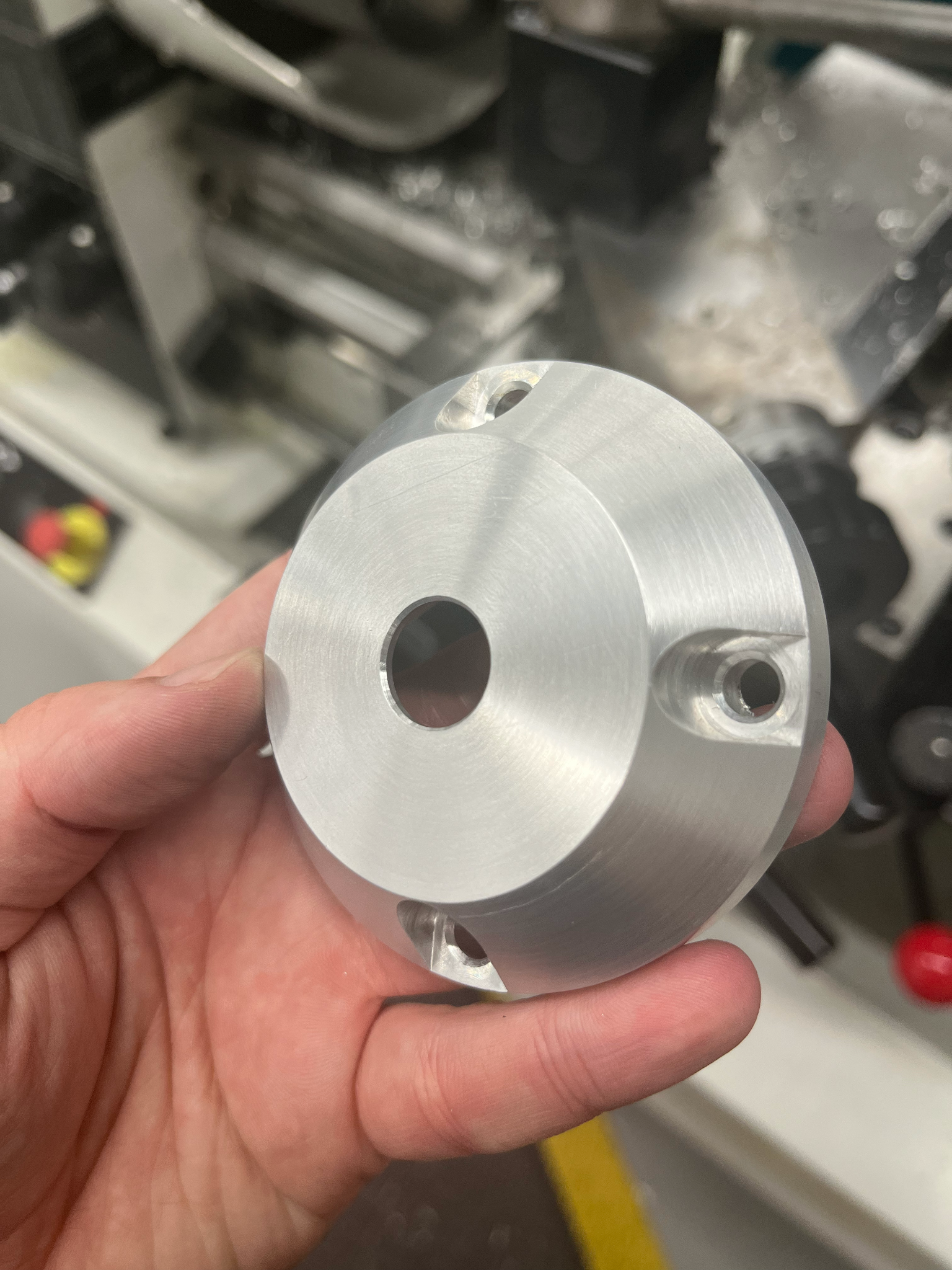
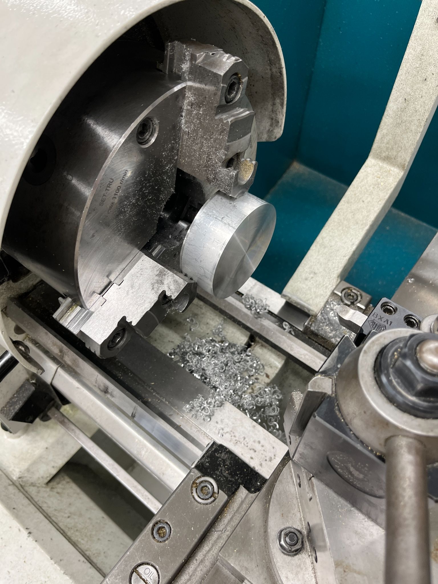
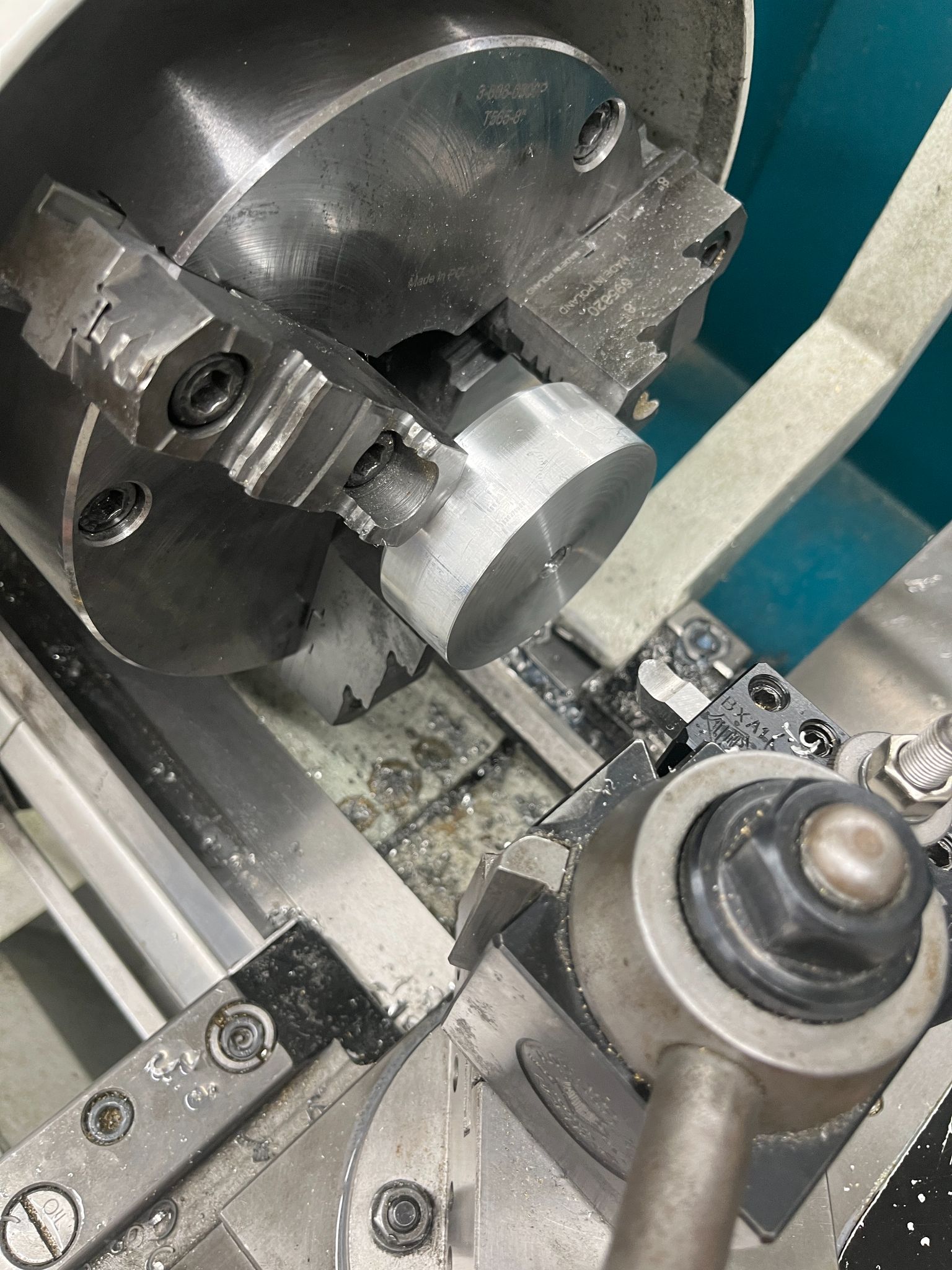
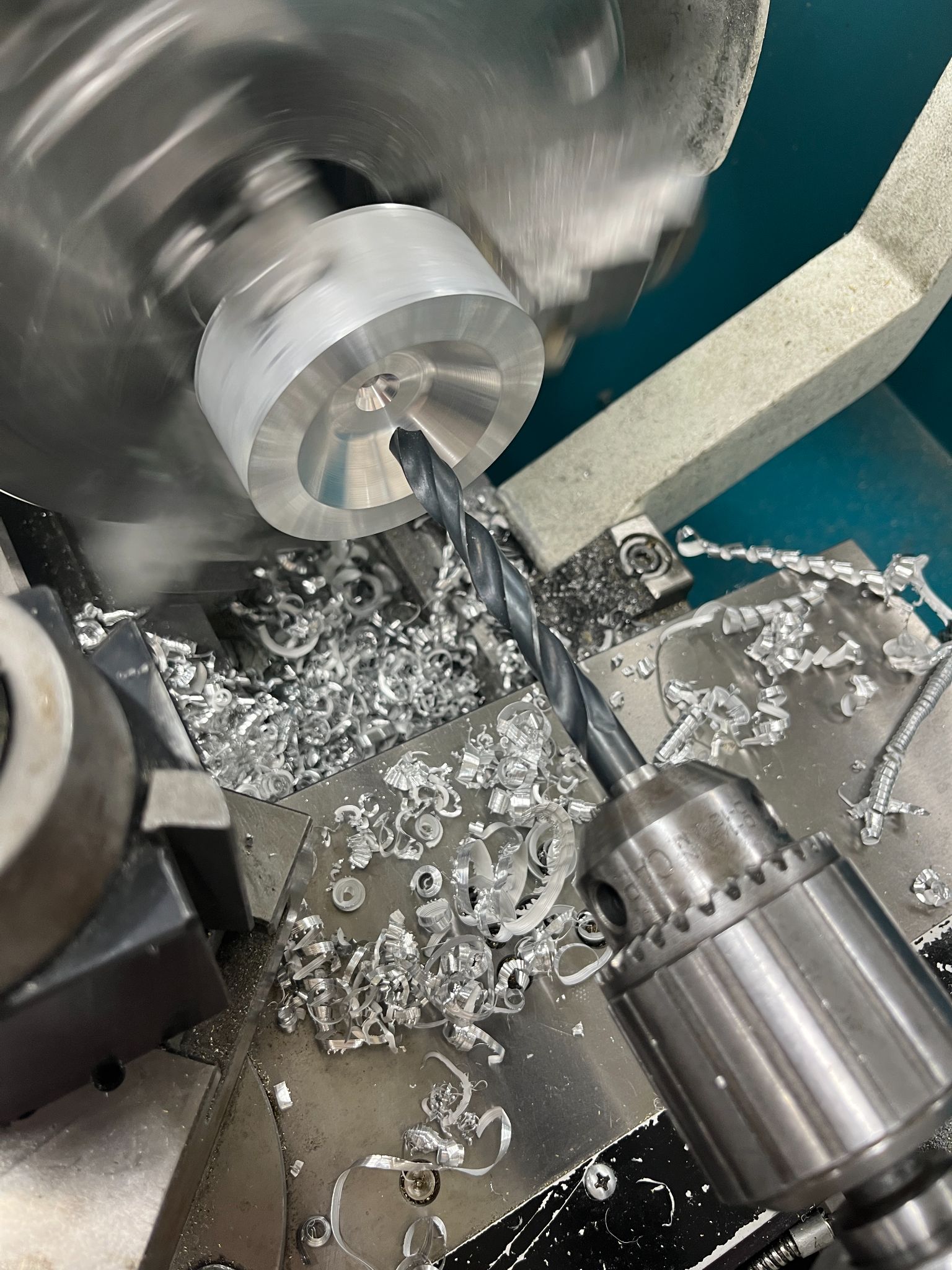
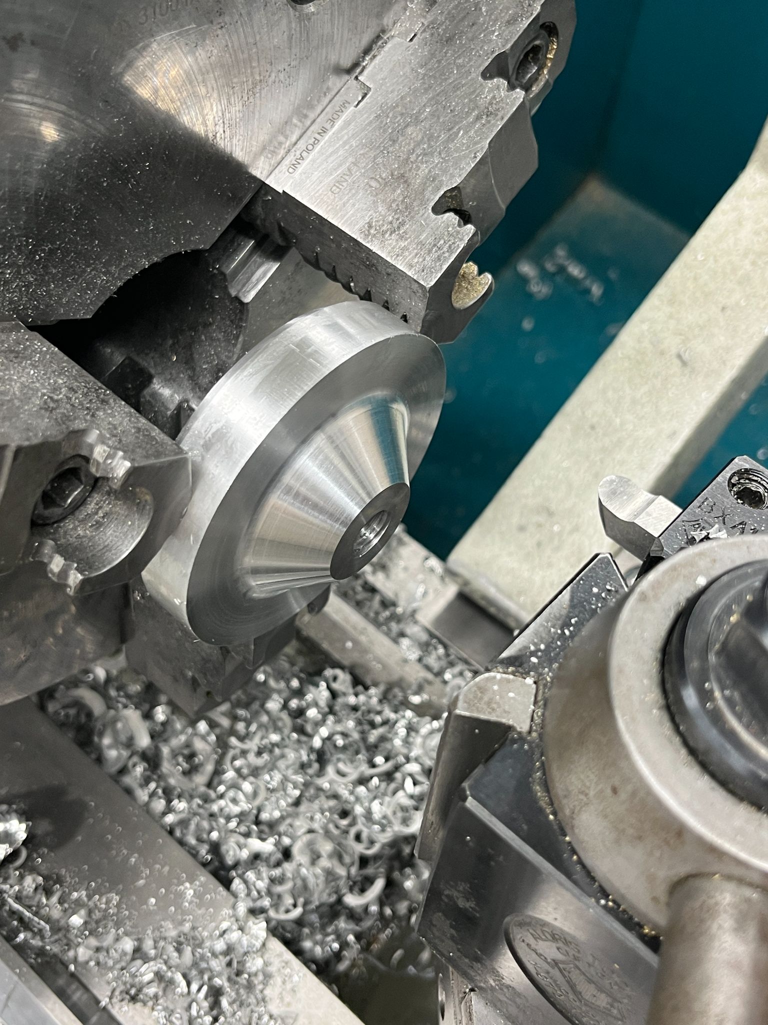
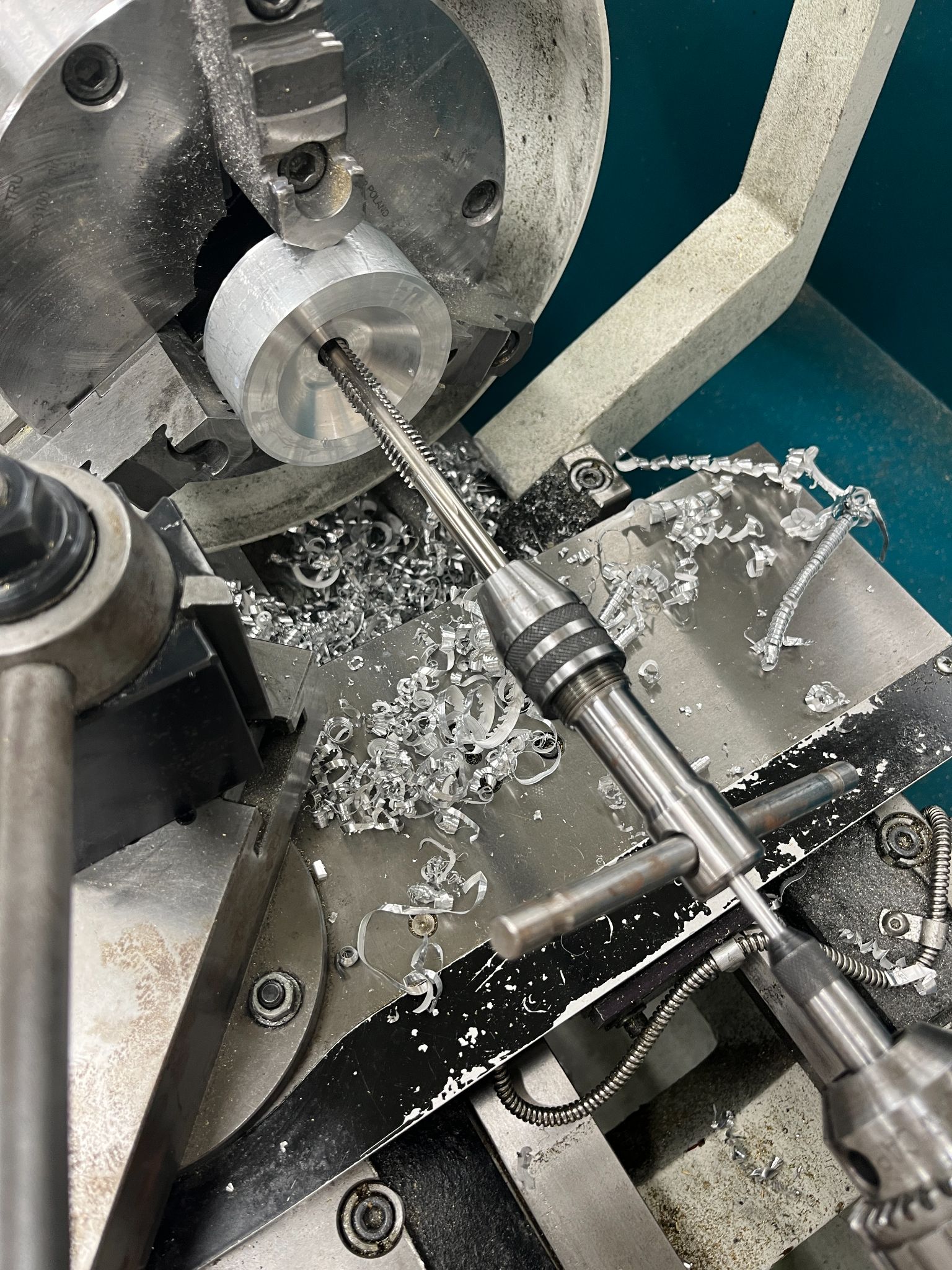
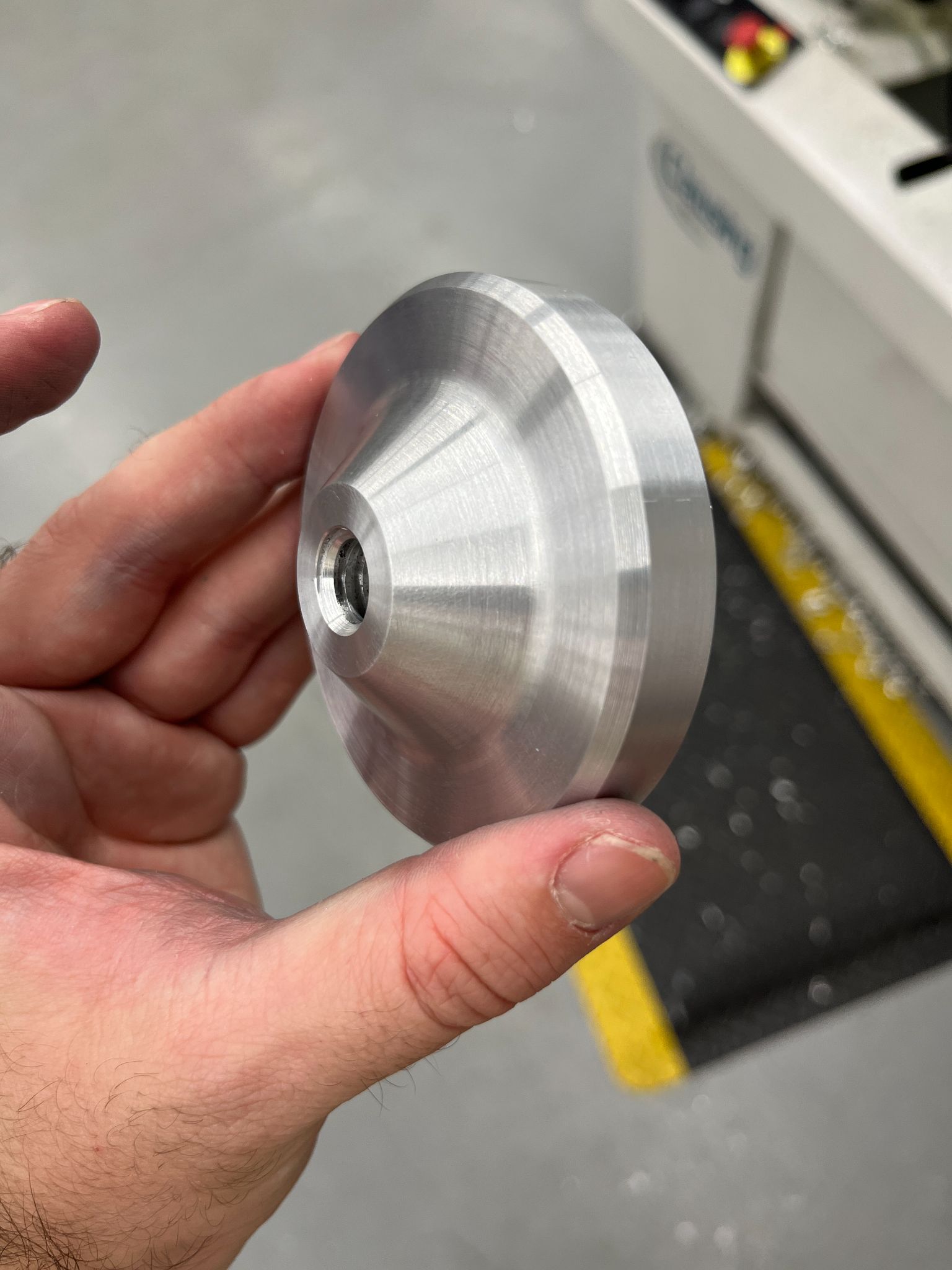
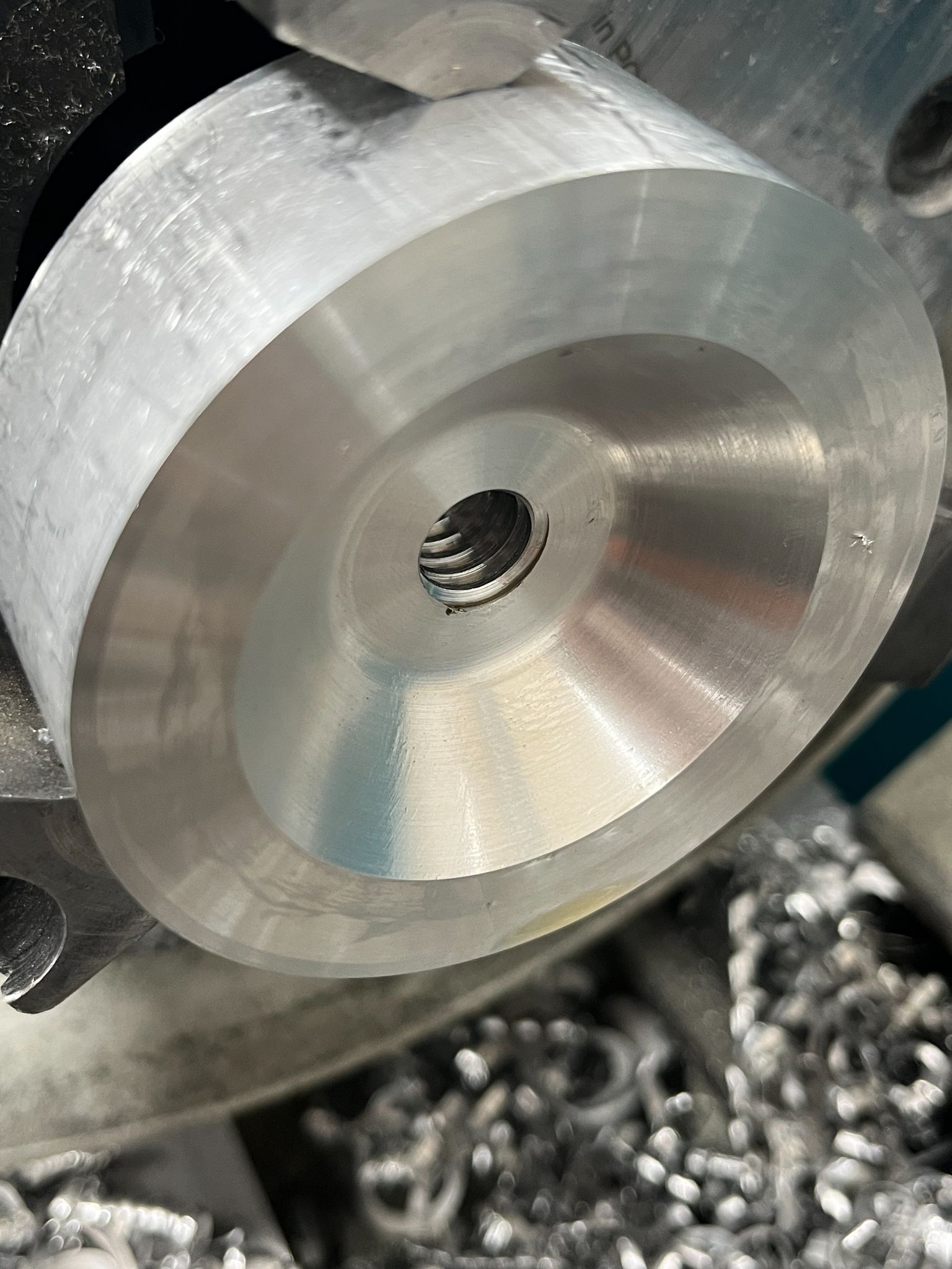
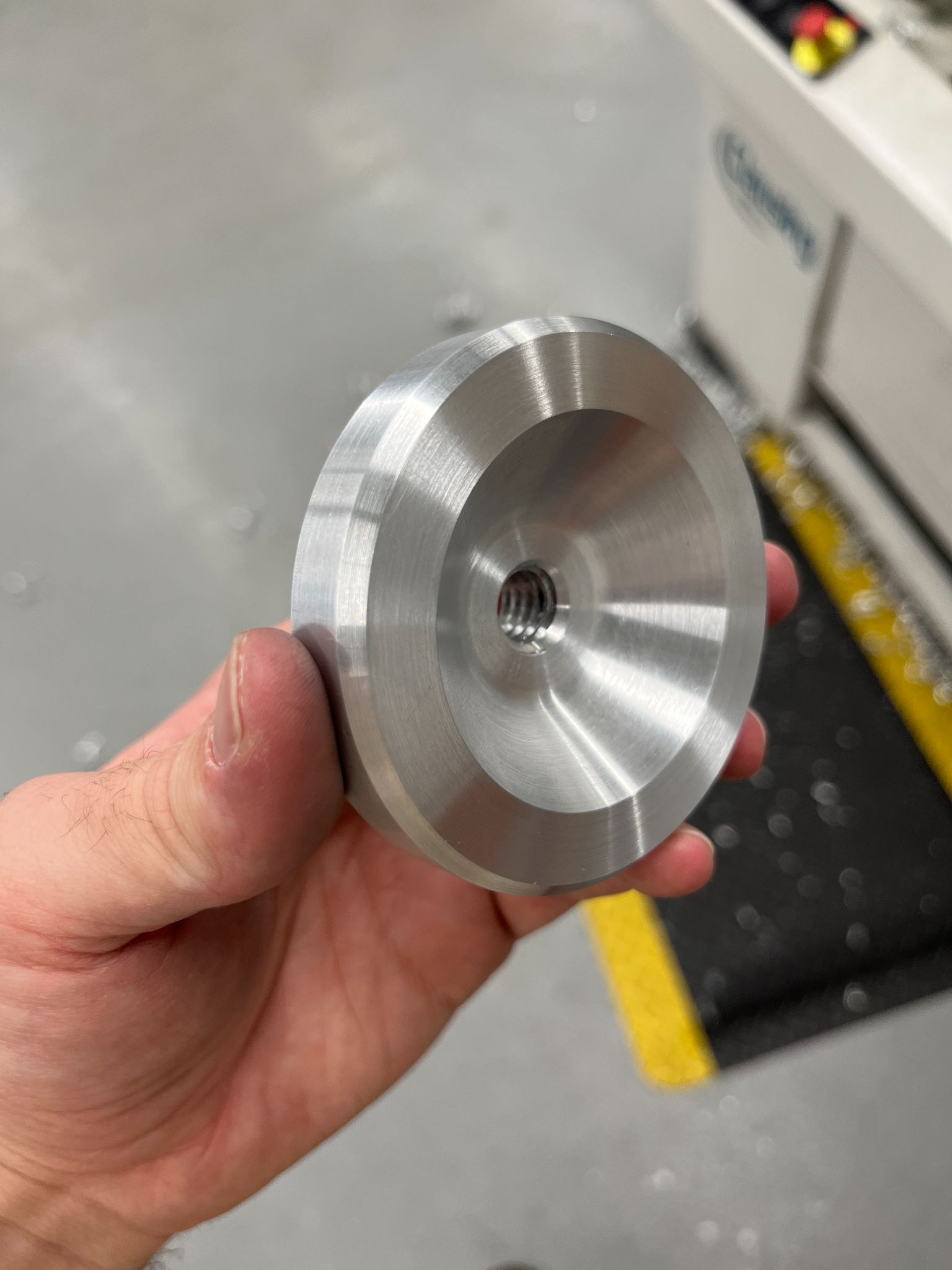
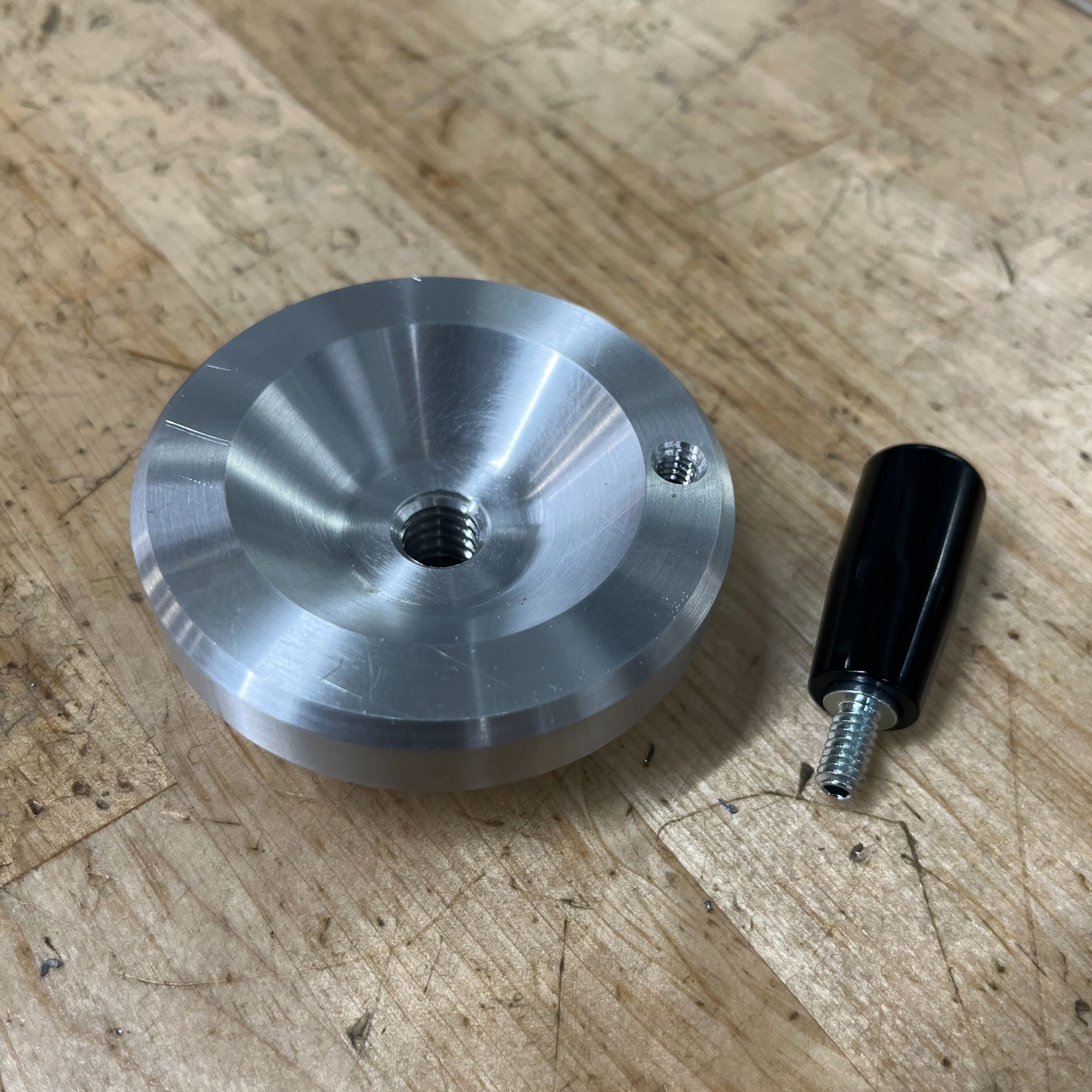
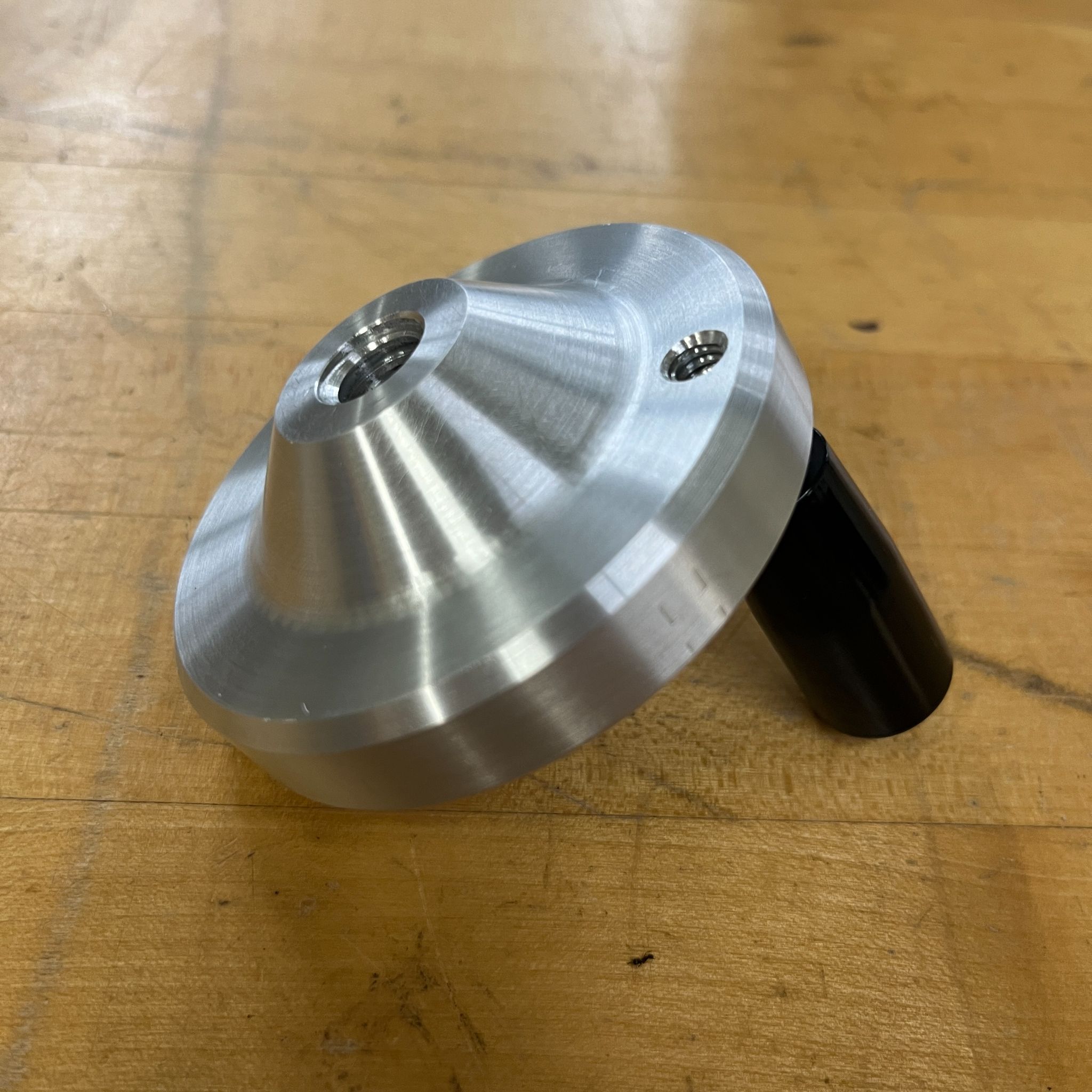
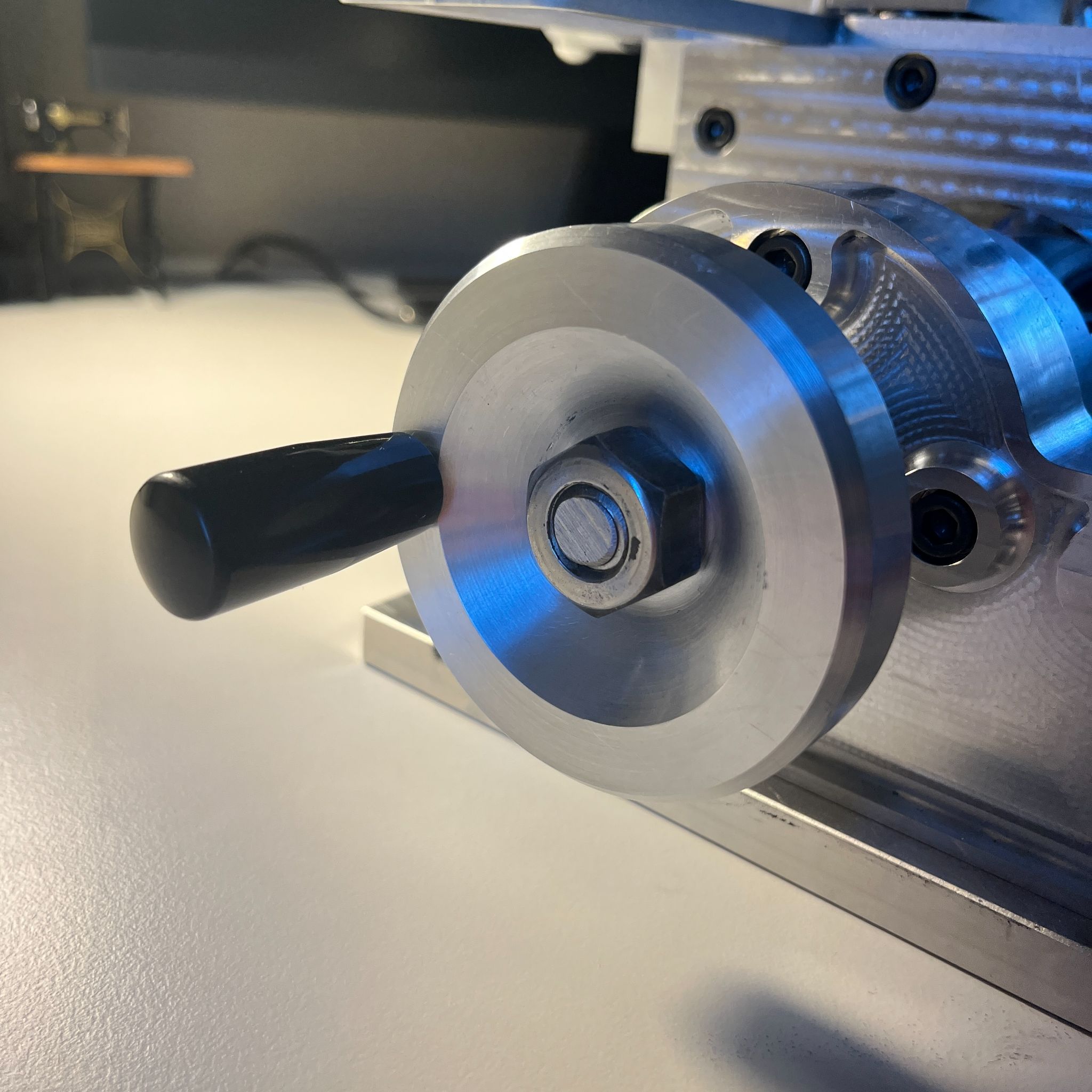
The last part that the groups in this class make is the handle for the axial travel. Typically, groups end up 3D-printing the handle, which I thought was an insult to the lathe's all-metal build. I bought a cheap revolving handle and machined the handle disk with no real drawings to go off from and it is by far my favorite part on the lathe.
Performance and Conclusion
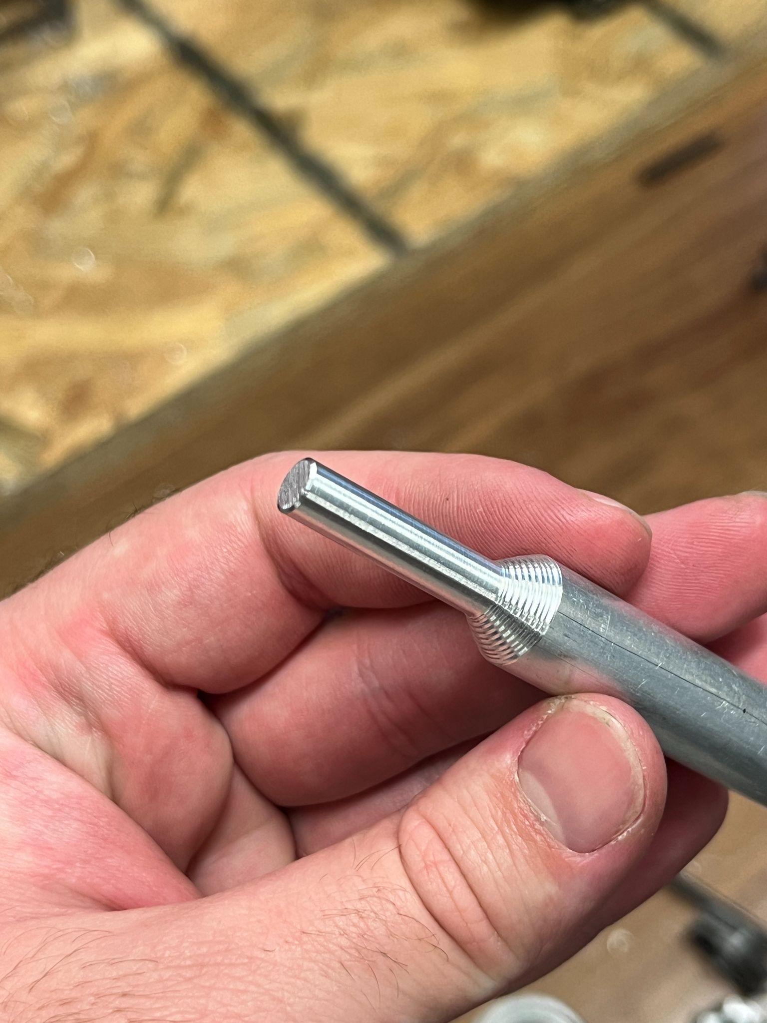
Our test was to turn a 1/2" round of aluminum down to a 1/4" in diameter. Both speed and accuracy were recorded. All of the groups had to work on their lathes till hours before the test, so groups began to care less about cutting with speed and accuracy, and more about just cutting at all. We took around 30 minutes to turn down our aluminum stock and cut 11 thousandths of an inch too small for the final diameter. Our results were very poor for a few reasons. There was some binding in the linear rails and bushings, which made moving the tool along the Z direction very difficult. Our single-point cutting tool we ground had aggressively large rake angles, which if we made a depth of cut larger than 20 thousandths of an inch, the cheap chucks would fracture. Thus, we had to make many shallow cuts to get down to dimension. Lastly, on the final pass, after measuring the diameter to be 11 thousandths of an inch too large, I moved the dial 11 thousandths but forgot that the dial shows the change in radius and not diameter. However, our surface finish was great, the dimension we cut to was systematically accurate, and a simple tool change for a tool with a smaller rake angle would have greatly improved the results.
