Mountain Bike Load Cell Test Fixture
The goal of this club project was to create a way to measure real-time loads exerted on a bike frame and use those measurements for a finite element analysis on future frame models.
The design we chose to go with was essentially just a very strong hinge. We designed the fixture to be easily installed on any bike with the same head tube type. We also designed it such that the fixture would protect the load cell from bending and ensure that the load cell would experience the actual axial loads experienced by the front of the bike. My teammate designed a 3D printed "water bottle" to encase the battery and other electronics for recording the data, to be conveniently stored in the bike's bottle cage.
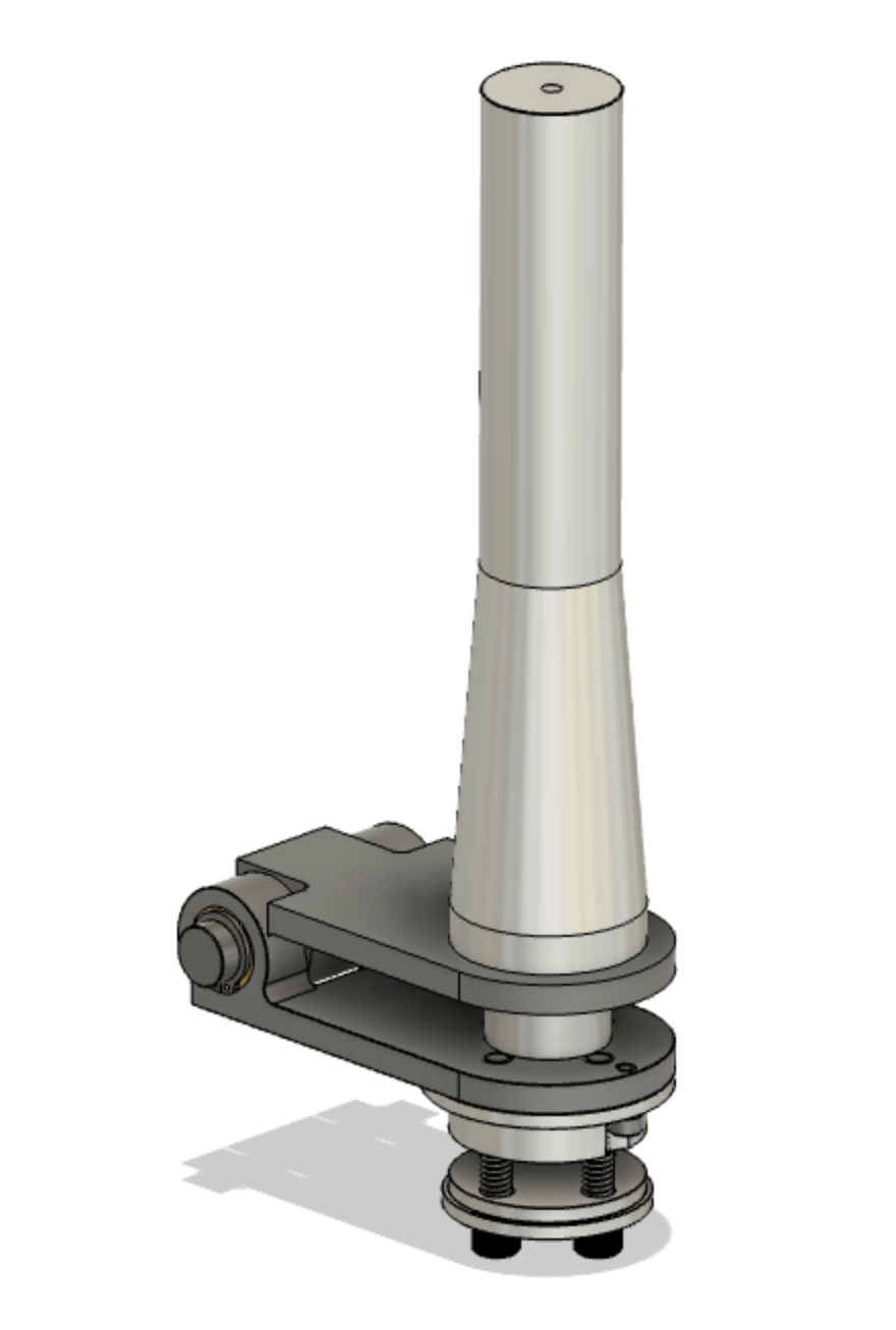
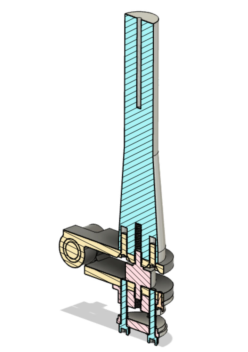
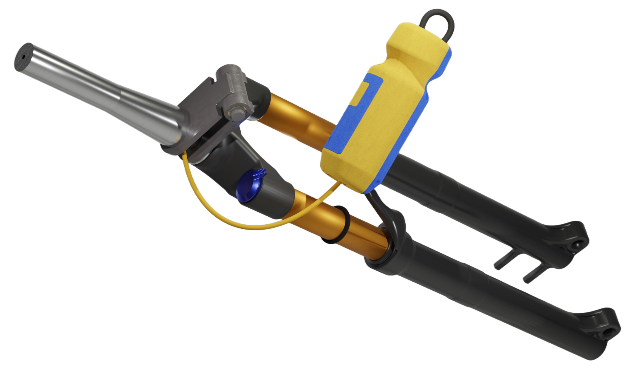
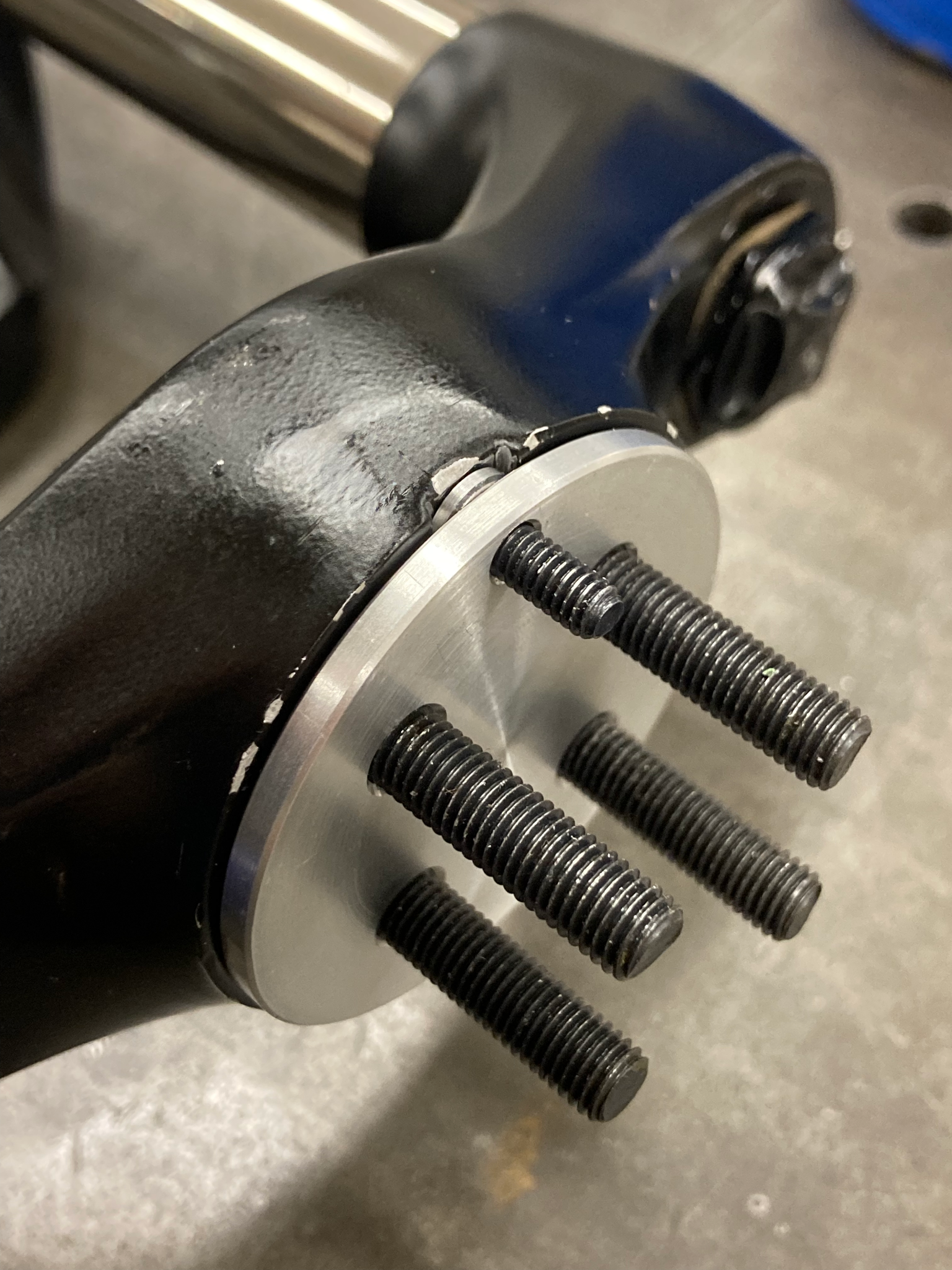
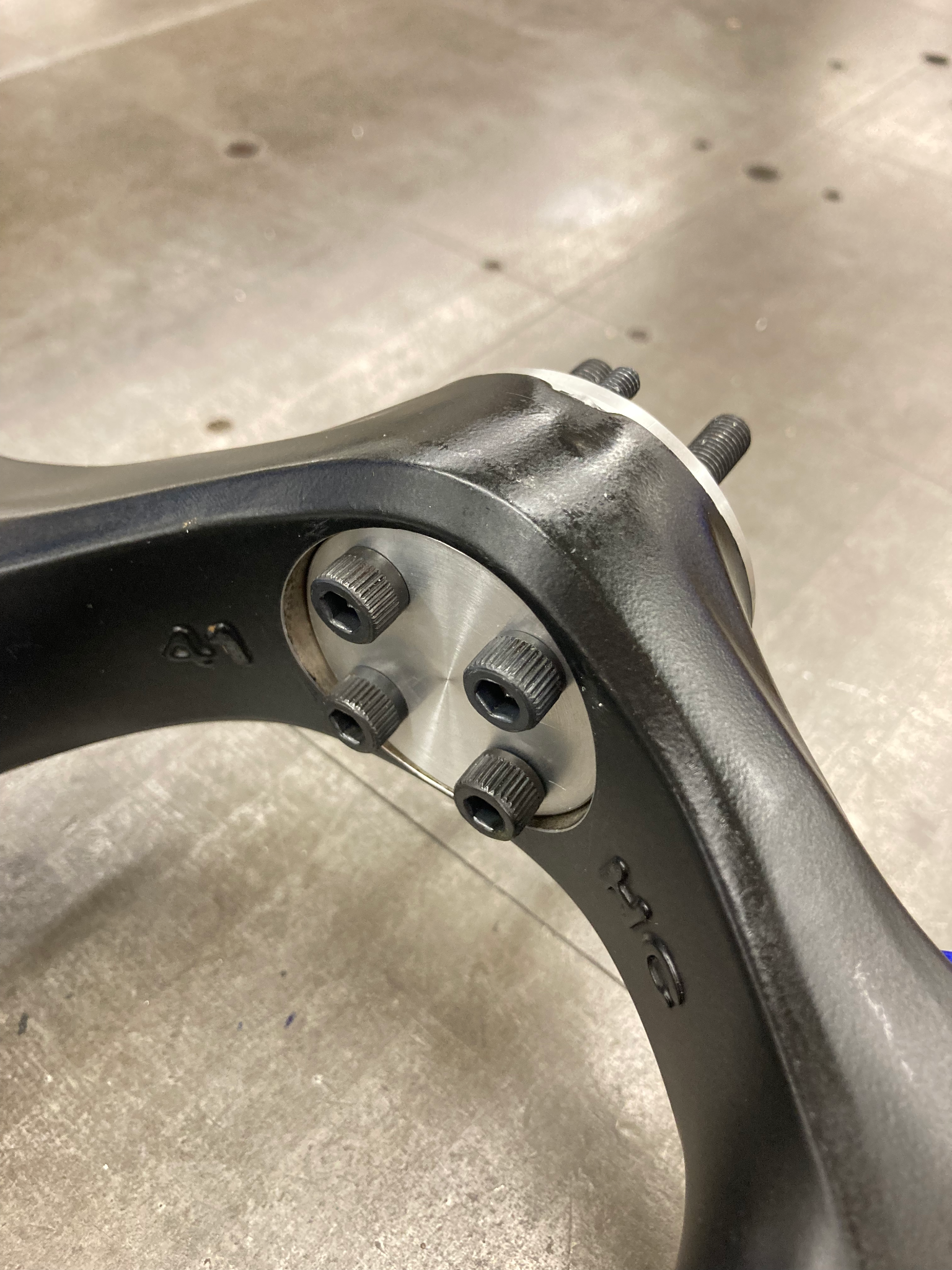
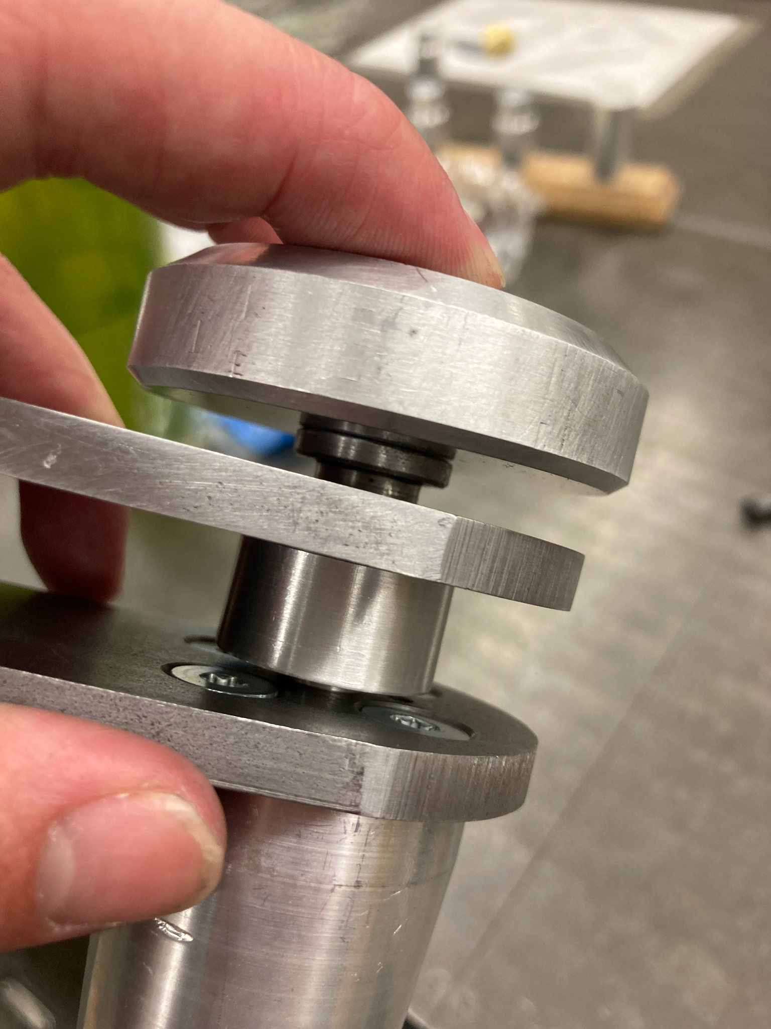
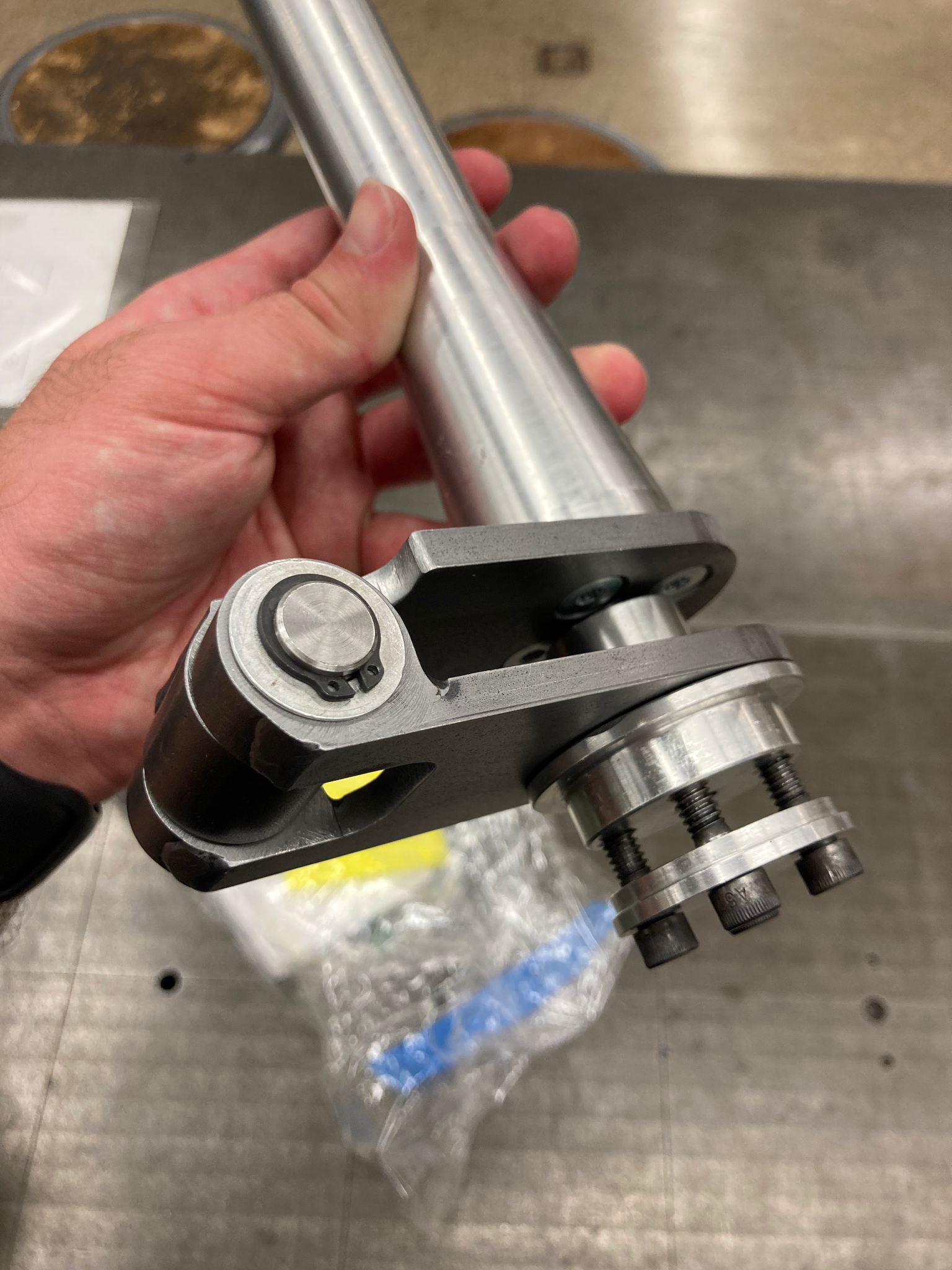
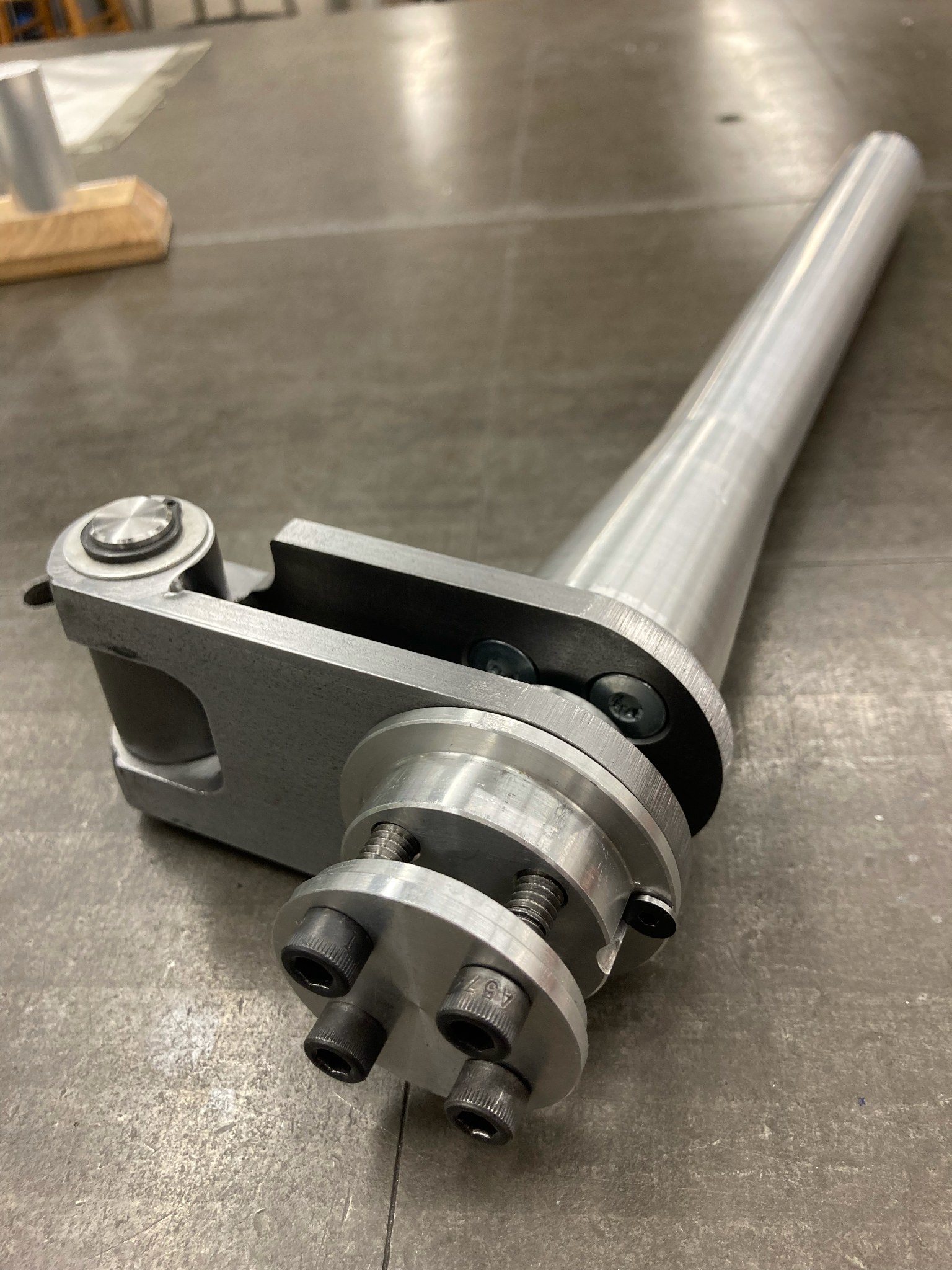
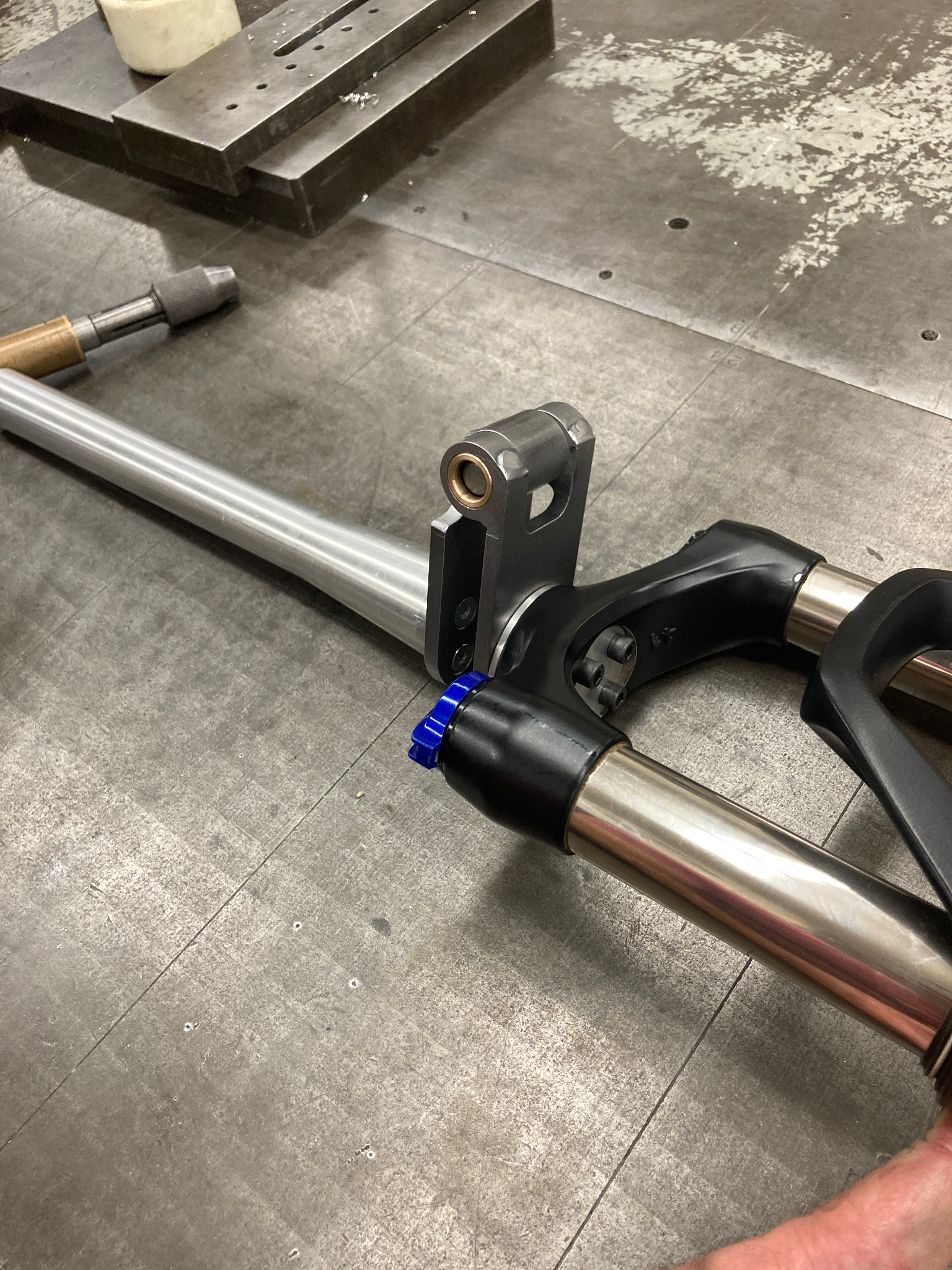
The head tube would be turned from solid aluminum to be easily secured to the hinge. The hinge would be made from steel plates, steel rods, and brass bushings. The bottom of the hinge would be fixed to the crown of the front fork using machined aluminum caps and bolts.
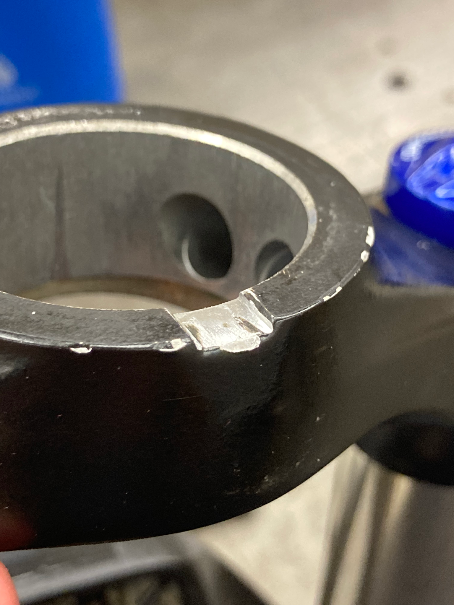
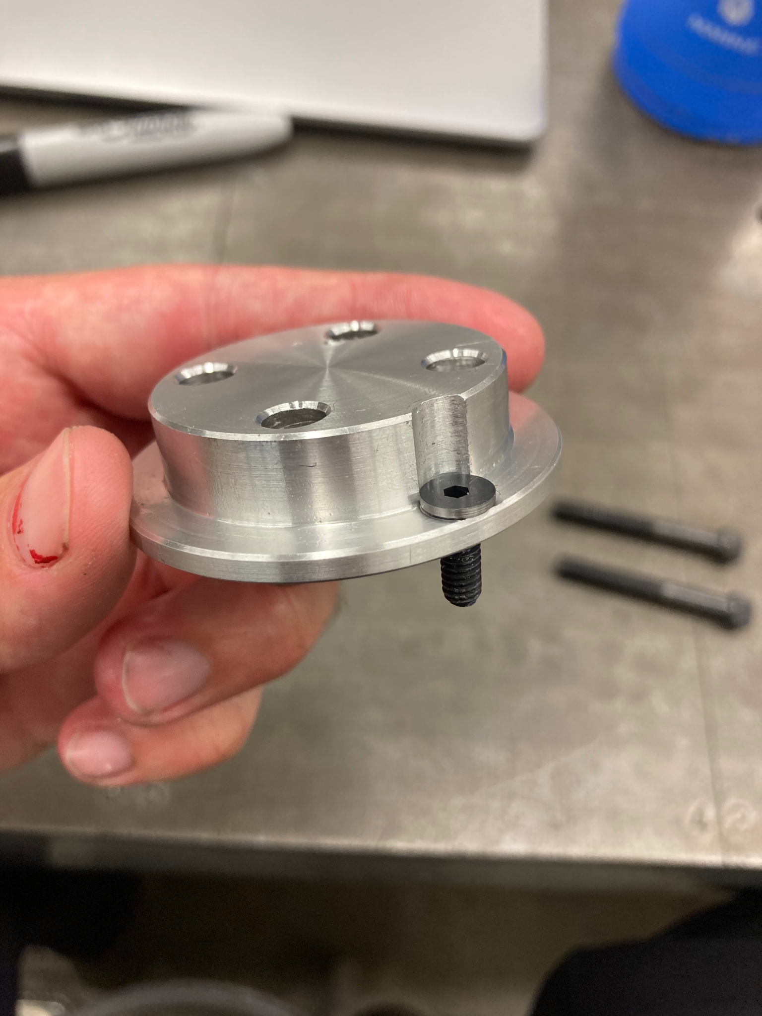
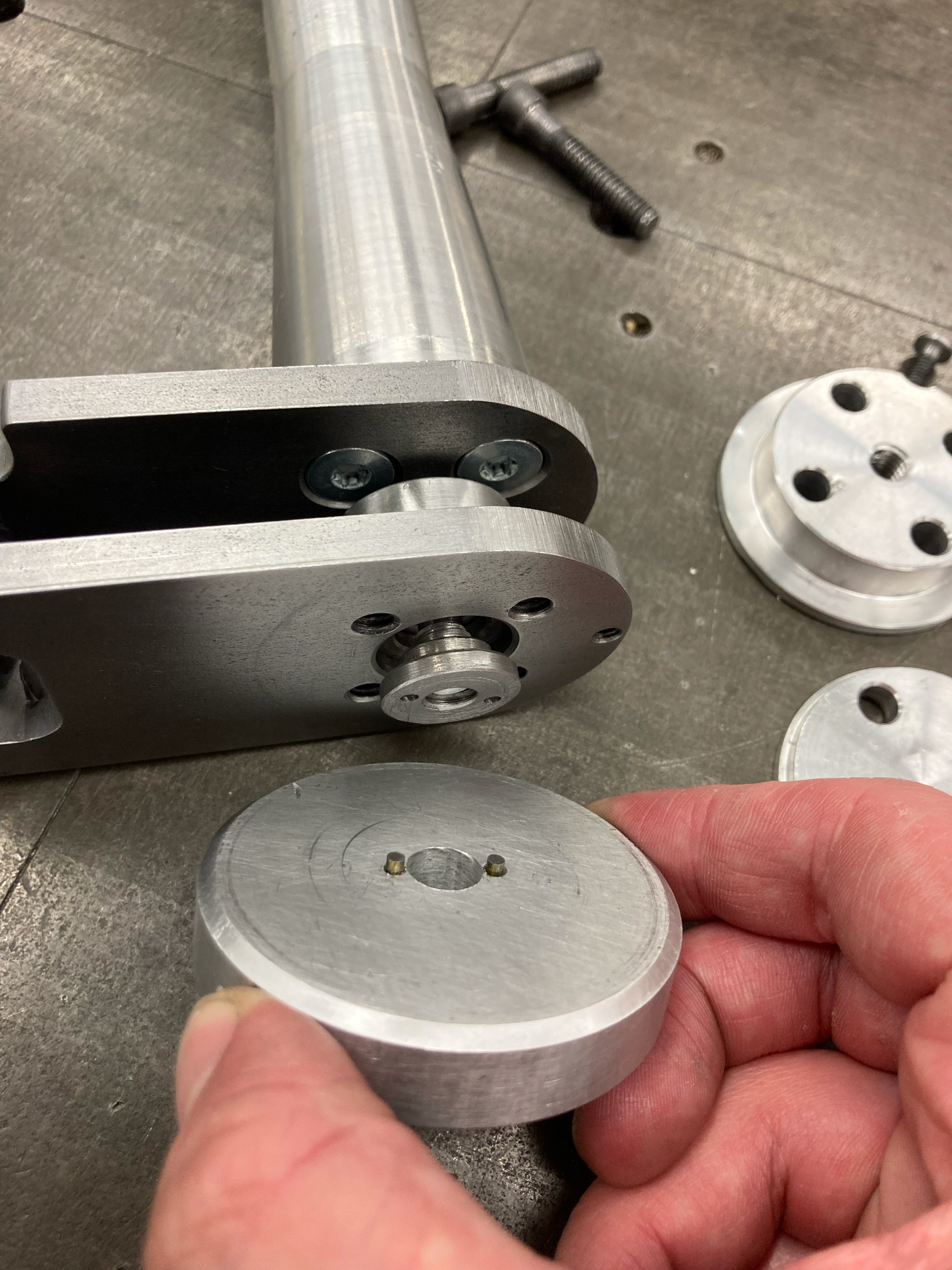
Below you can see that I filed a slot into the crown of the fork so that a small screw could fit snugly in the slot to help resist rotational motion.
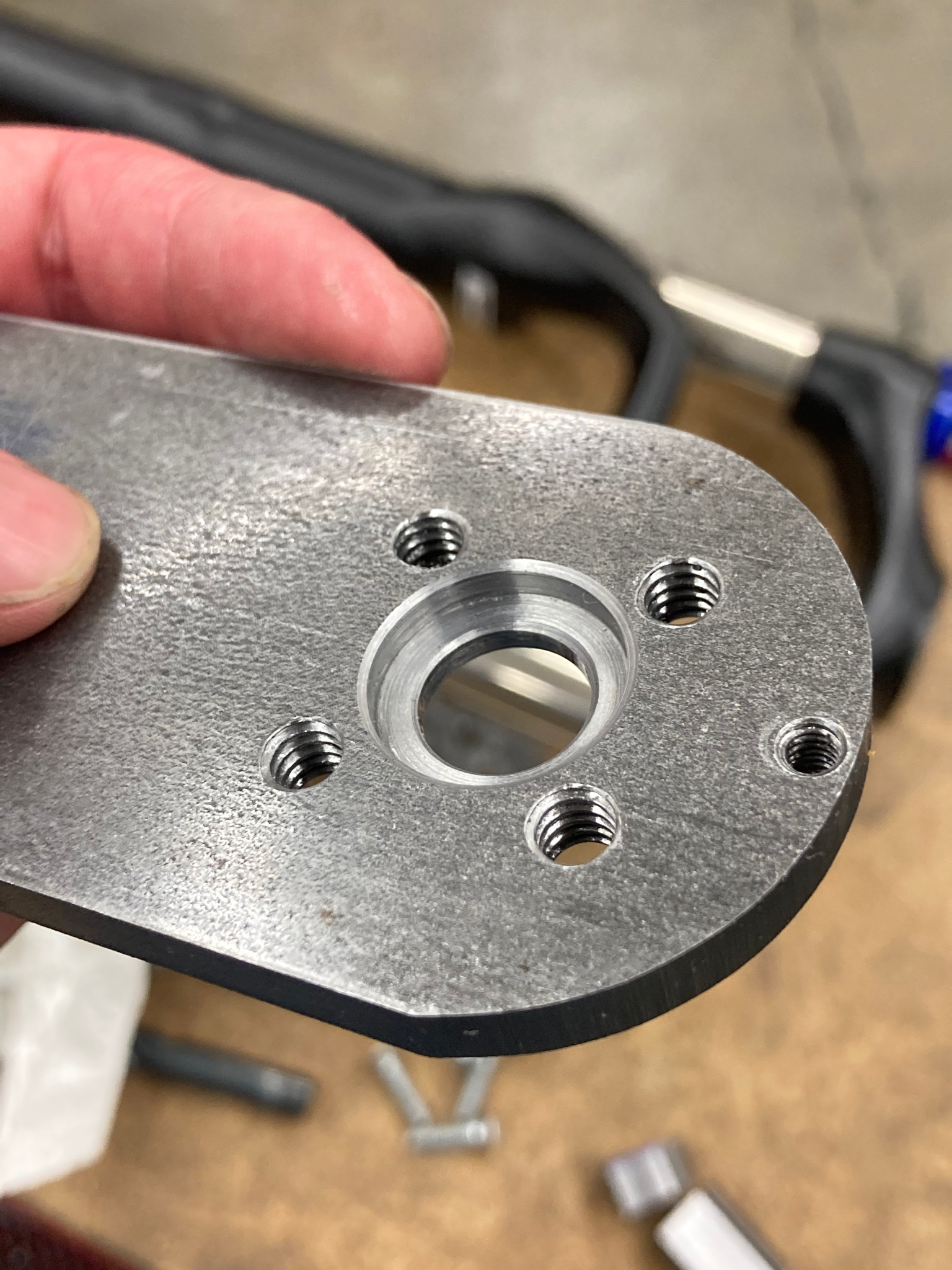
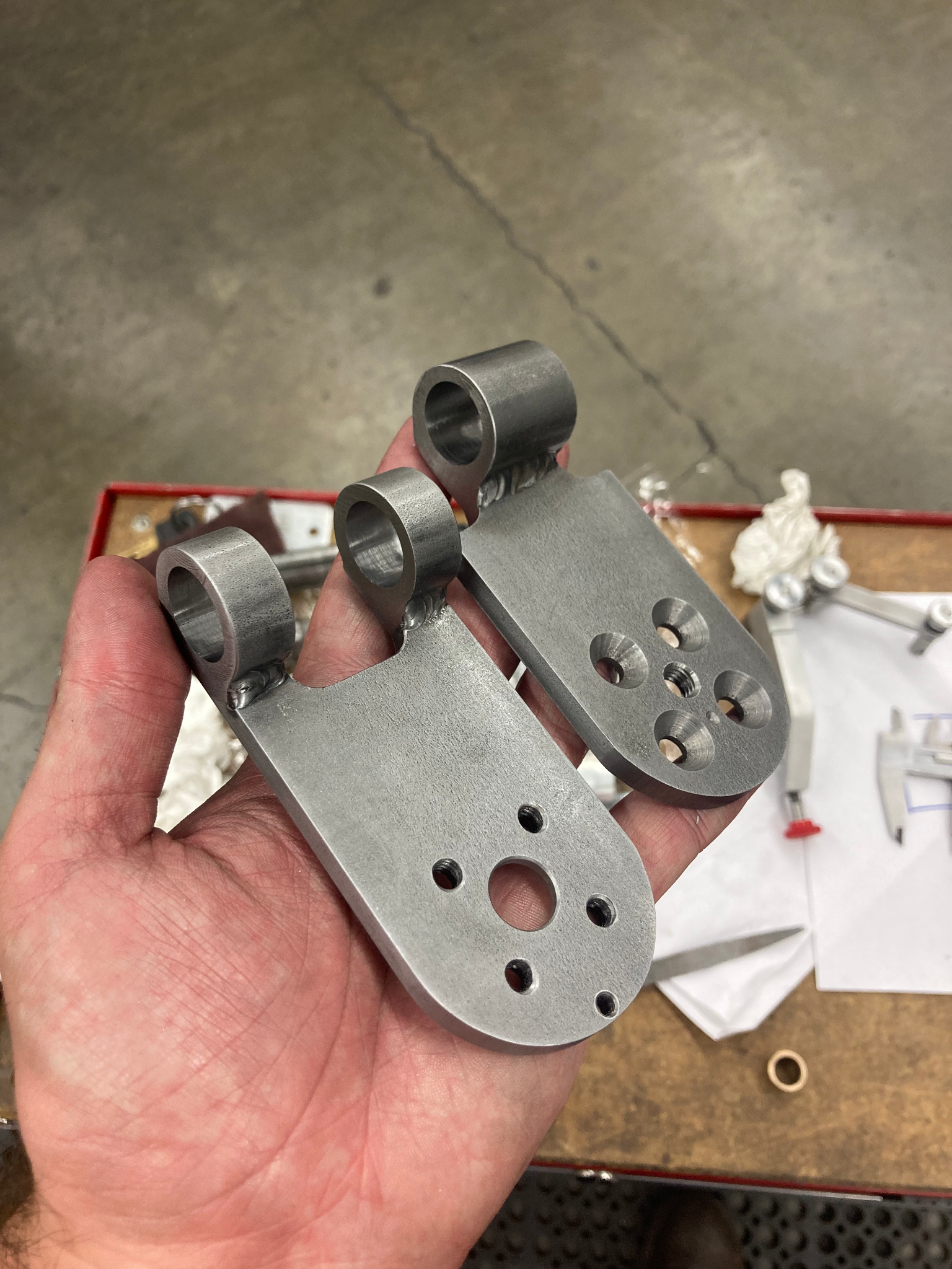
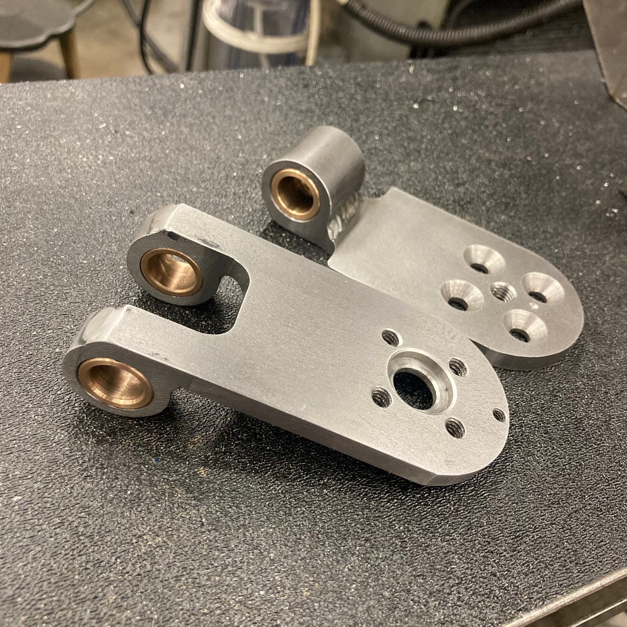
The steel parts of the hinge were made by welding steel rods on to the plates before the final machining. My teammate welded them and I machined them.
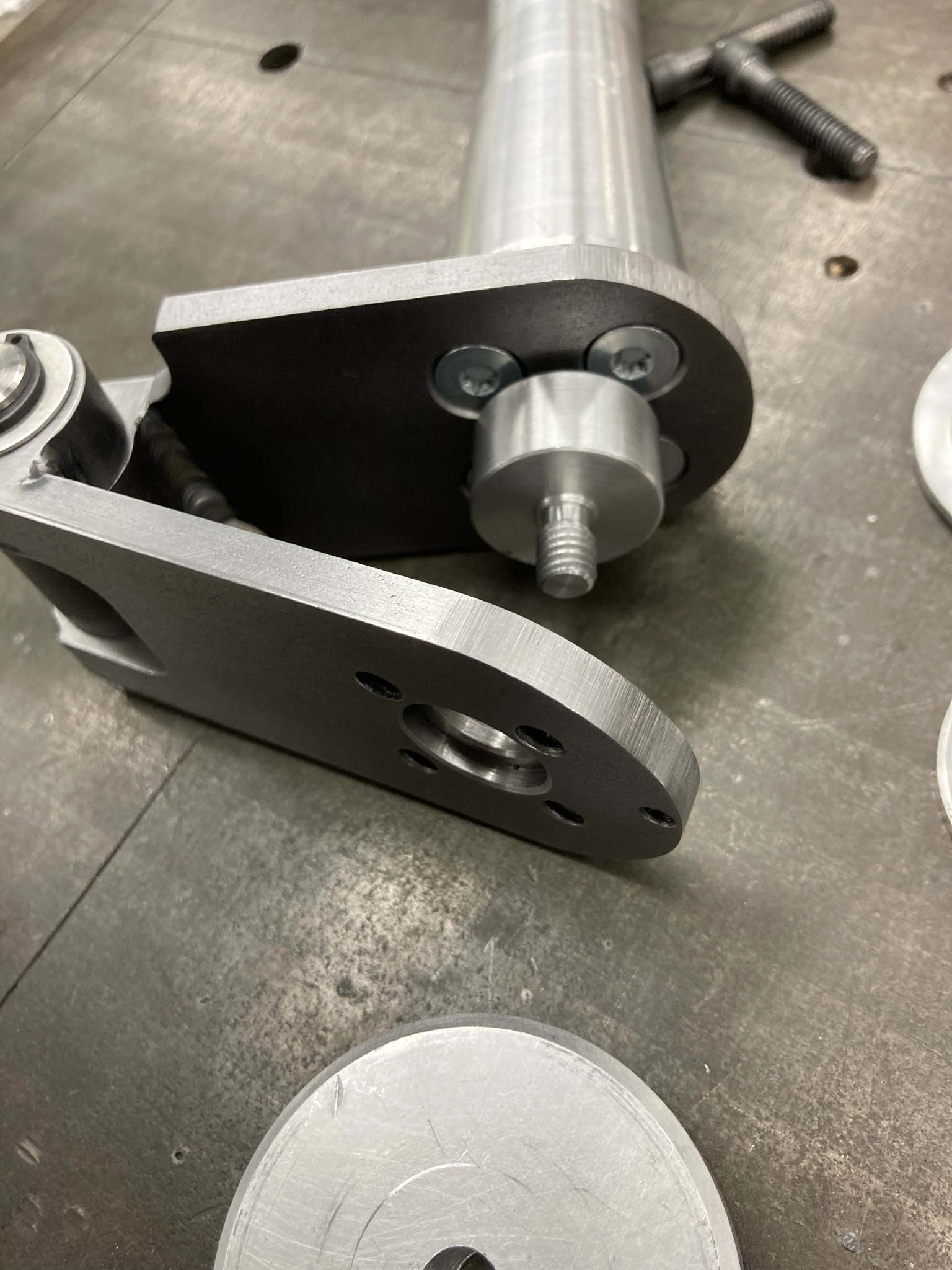
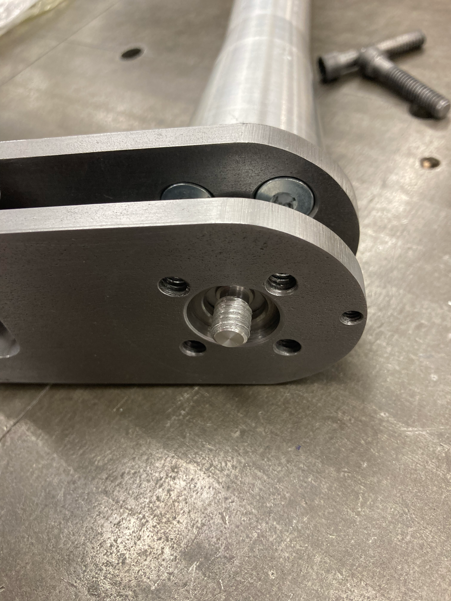
We realized that the load cell would be impossible to install as the screwing on one side would unscrew the other. So we made it easier with a small screw-on cap insert, assisted by a homemade tool to screw it tight.
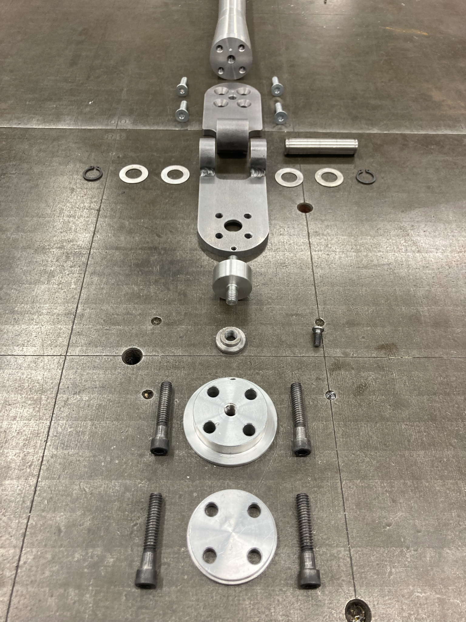
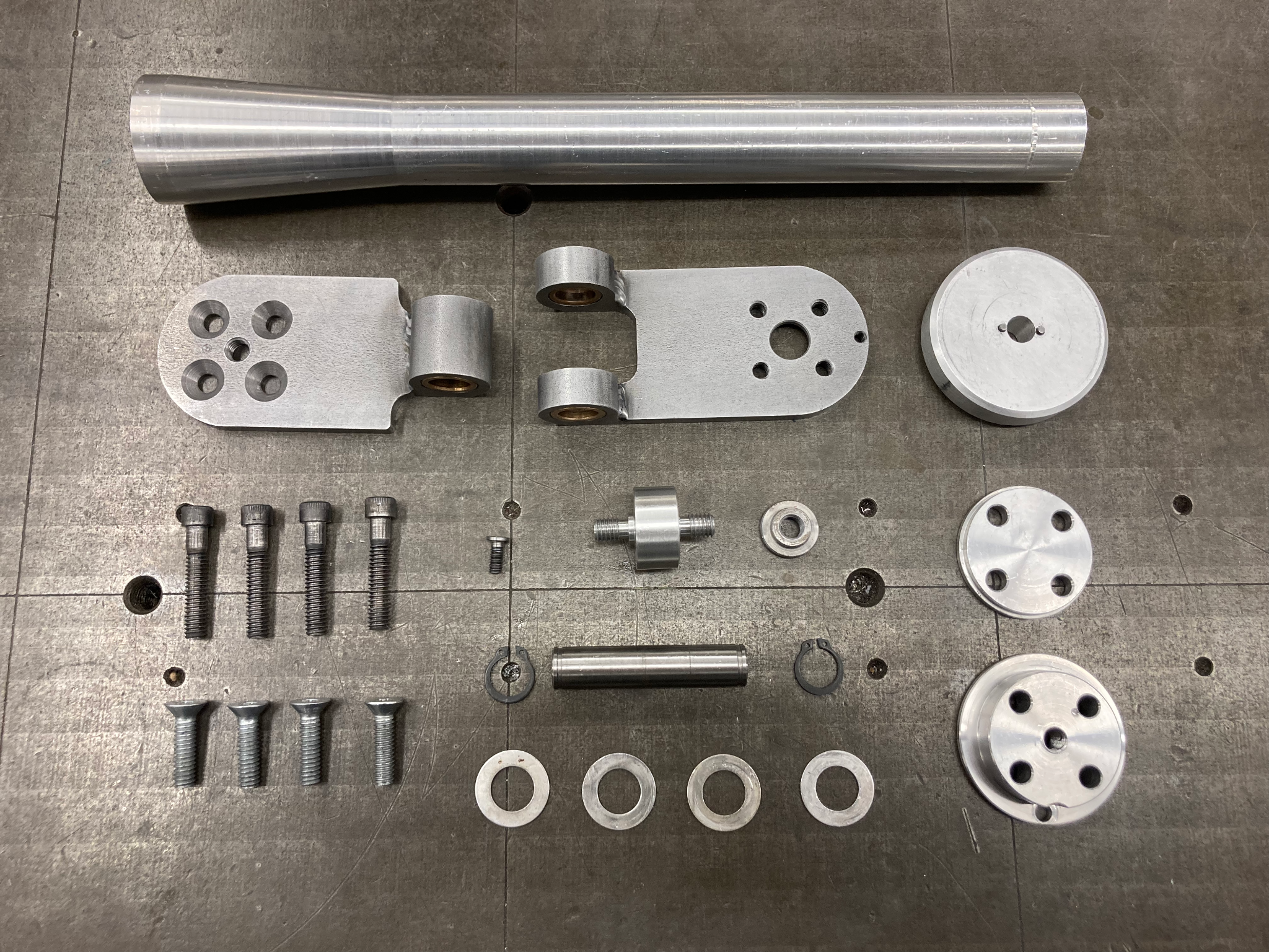
Here are all the parts we made and on the left is an exploded view of the assembly.
Here it is all put together and on the bike fork!
Due to me and my other teammate graduating and no one willing to trust their bike for the first test ride, we were unable to try it out and get data from it. The testing fixture remains with the bike building club to be used for a future project.