Self-Balancing Robot
In our class on robotic locomotion, our group decided to focus on the concept of balance control for our final project. A single-link inverted pendulum balanced via a reaction wheel was the perfect introduction to understanding how a robot could use this concept to maintain balance.
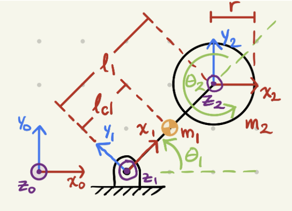
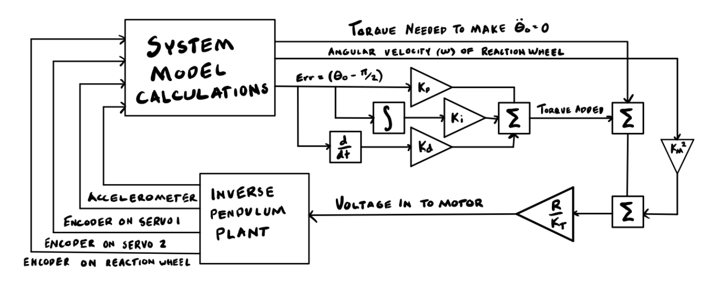
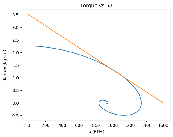
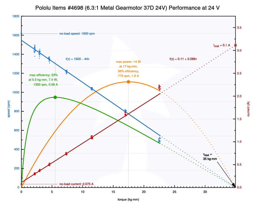
Through a Lagrangian dynamic analysis, we were able to make a simulation modeling the pendulum and its PID-controlled reaction wheel. With the simulation, we could see how different parameters such as mass and dimension values and PID constants could change the performance of the balancing. By obtaining the desired torque and rpm values from the simulation, we could determine what motor could provide that performance, while ensuring that the mass of the motor was small enough.

We worked iteratively with the simulation and design of the robot to ensure that our design changes did not weaken the balancing performance. The goal of the design is to have the reaction wheel have as much of its mass on the outer ring to maximize the rotational inertia, the body to be as stiff as possible to avoid unwanted vibrations at high speeds and torques, and to make things simple for fabrication.
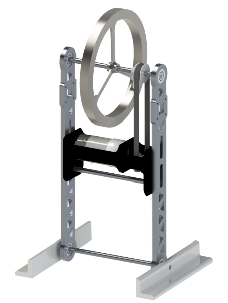
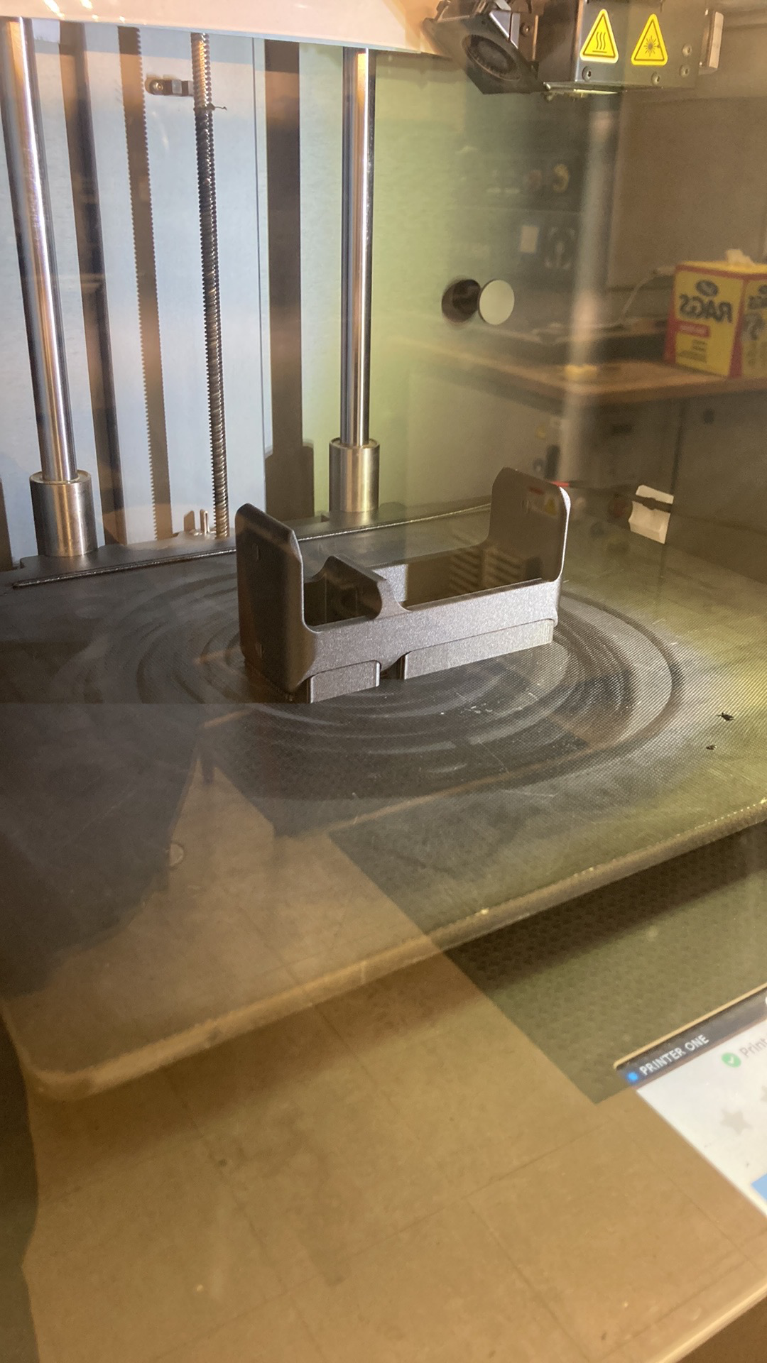
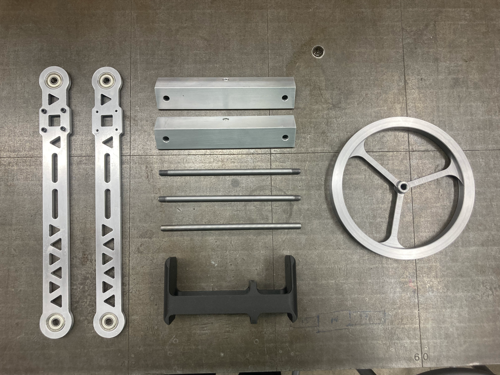
My role in this group project was partially in the design work, specifically in the design for manufacturing, and all of the fabrication. The reaction wheel would be manually machined from low carbon steel, the legs would be waterjet cut from aluminum, the motor housing would be 3D printed with a carbon fiber infused plastic, the connecting rods would be threaded and tapped from steel, and the base brackets be cut and machined from aluminum angle extrusions.
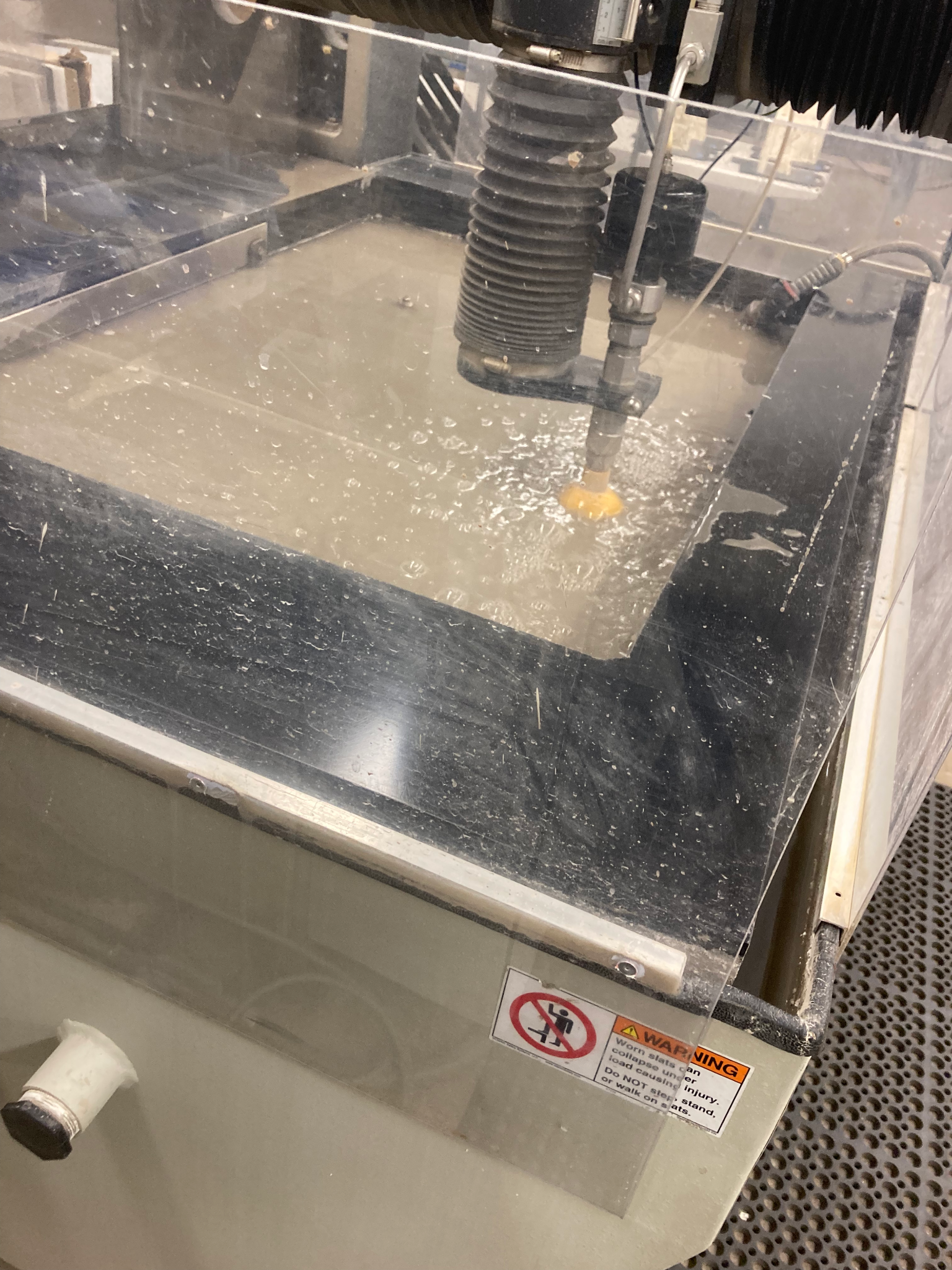
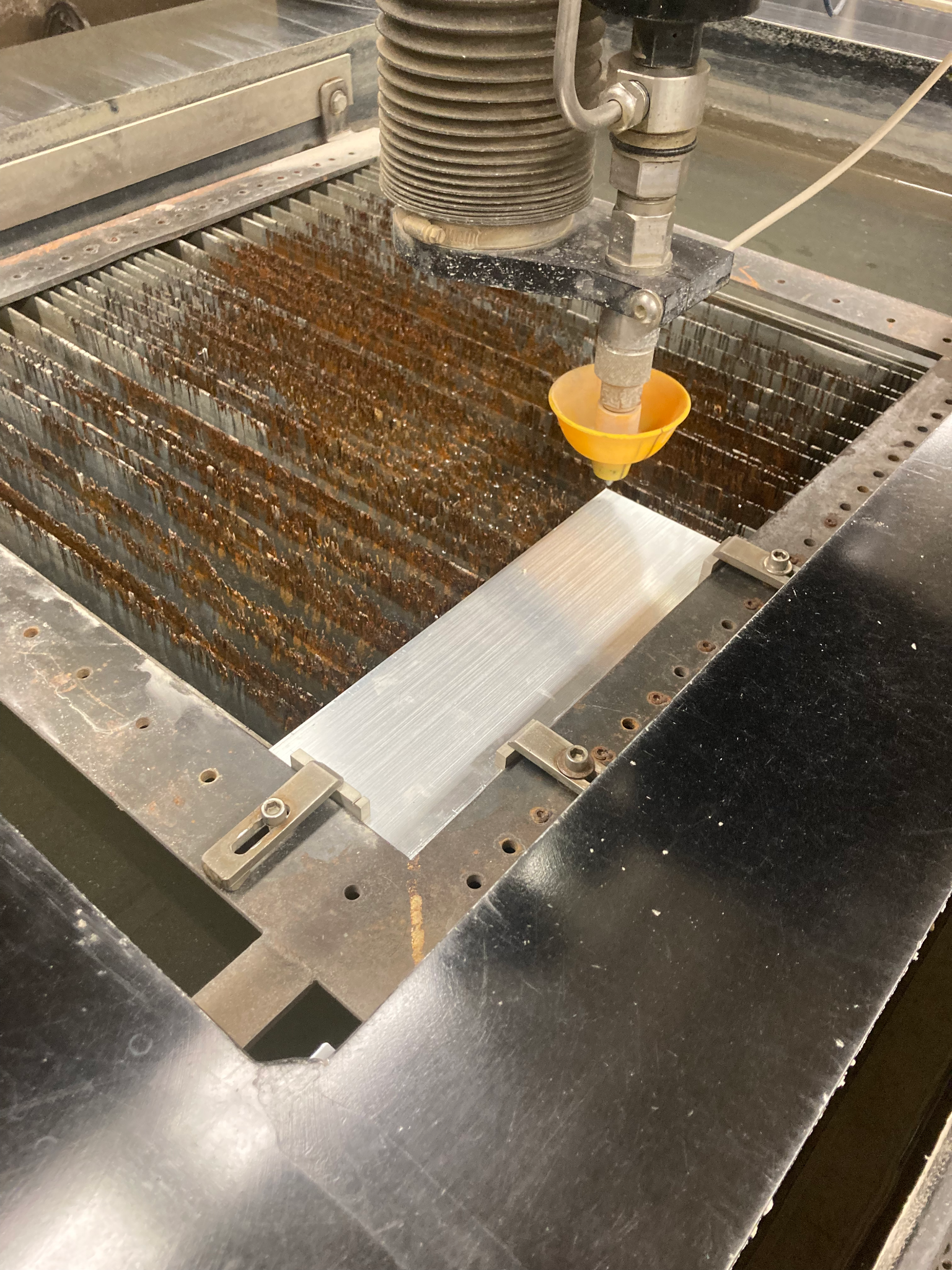
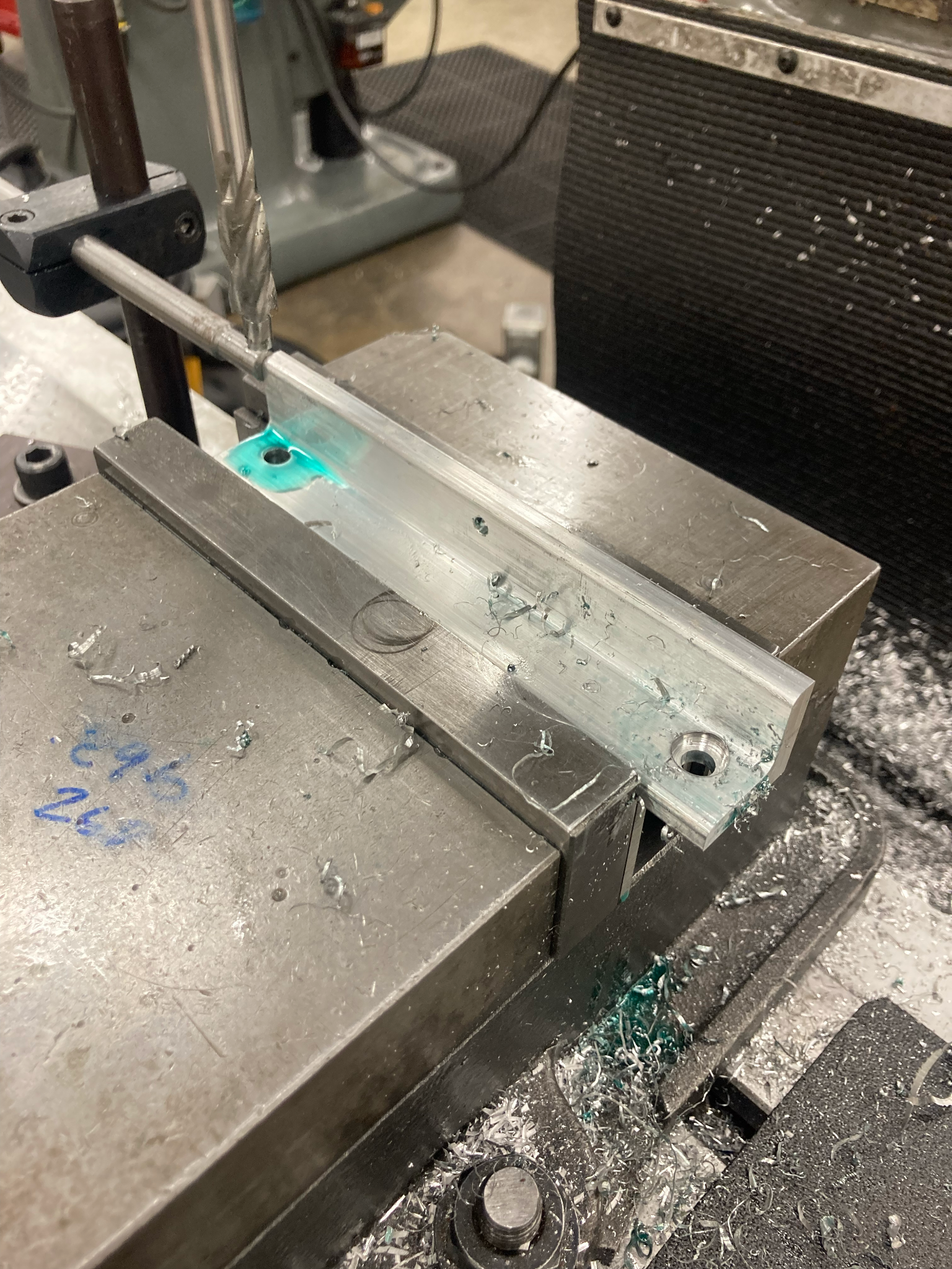
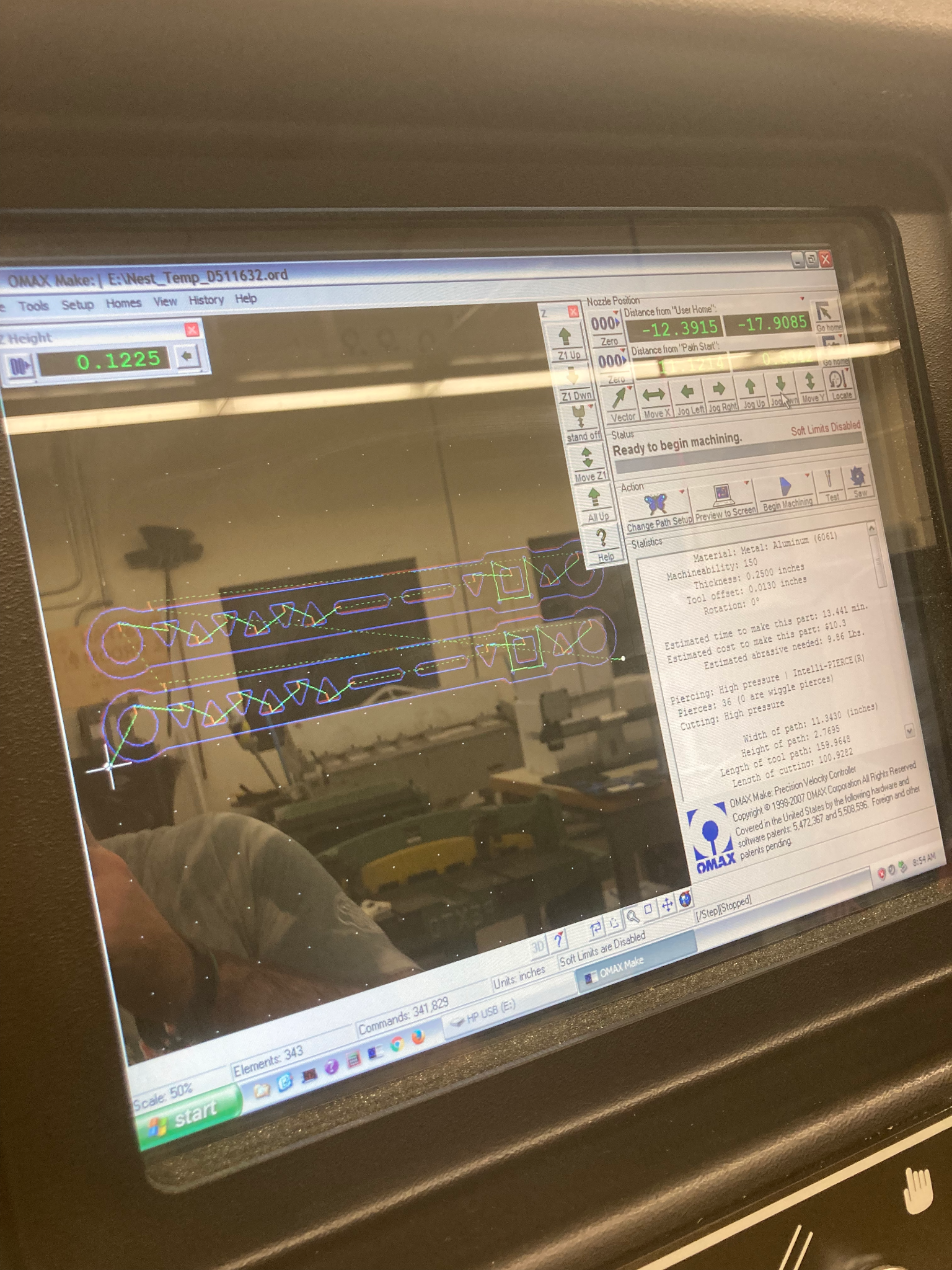
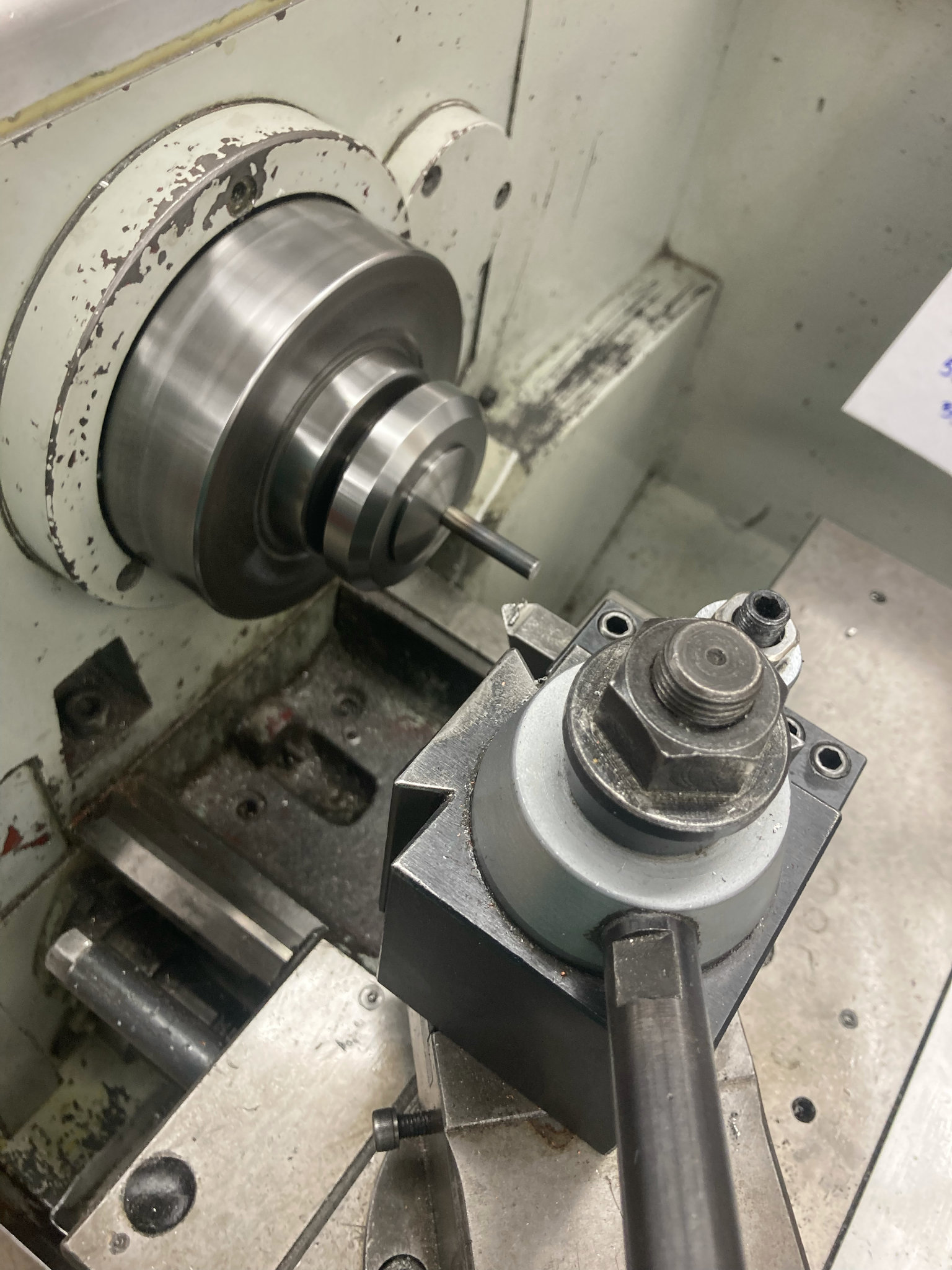
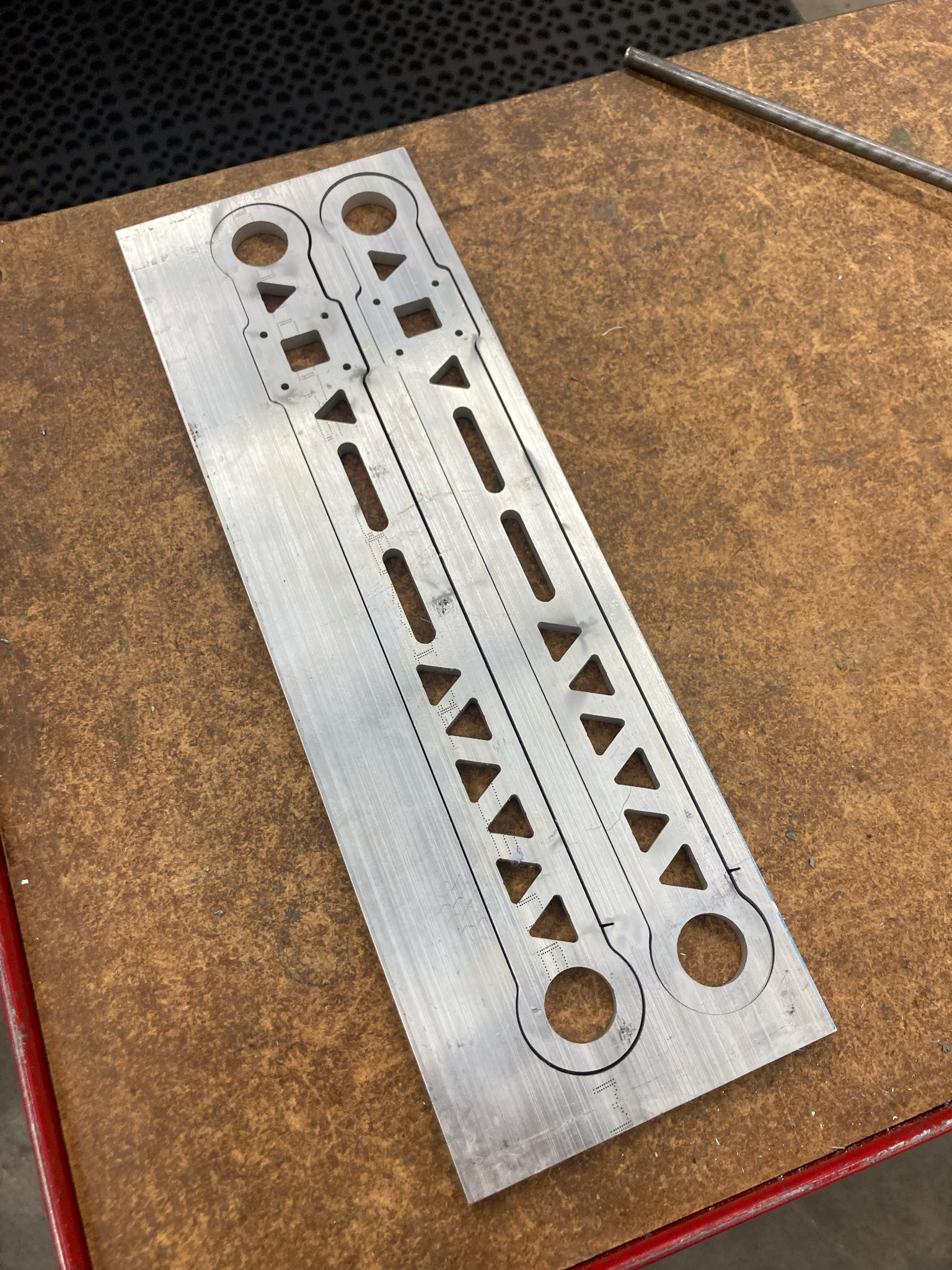
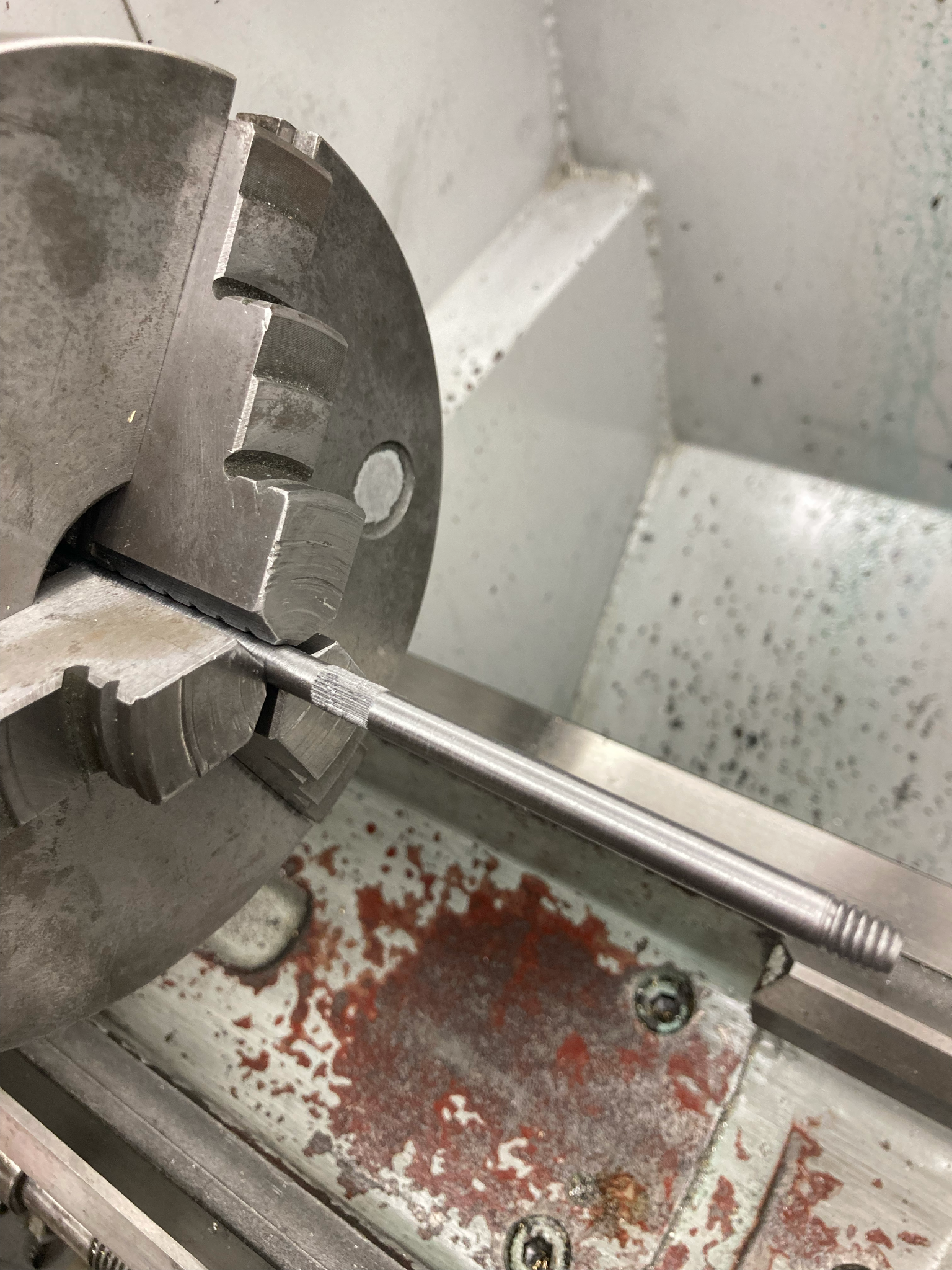
The reaction wheel took me four days of manual machining to make. The geometry involving three spokes made it an ideal job for the water jet cutter. However, the cost of a steel plate large enough to allow room for clamps would have been about 50% more expensive. We chose to save money and challenge my manual machining skills. Fabrication for the wheel had to be carefully done to ensure it was balanced and ran true, thus dial indicating was used many times. Flip through the image slides for the machining montage.
Here are all the parts made and it all put together on a heavy aluminum base plate:
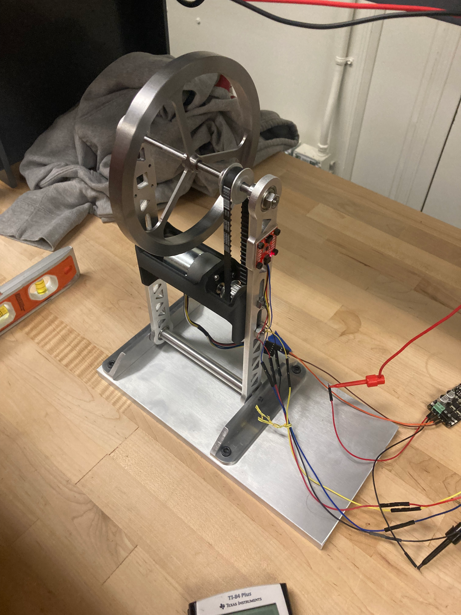
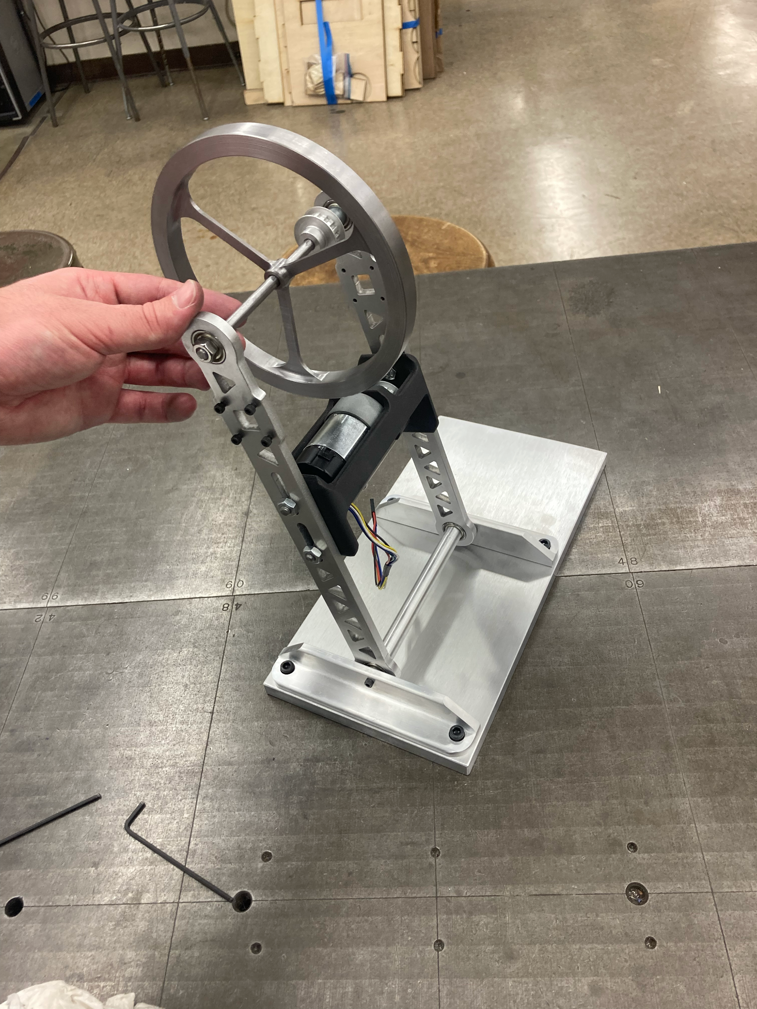
After a lot of testing and PID tuning here is a video of the robots performance: