Gait-Altering Robot
Objective: Engineer a multi-leg walking robot that utilizes a single motor for locomotion and a secondary actuator for steering by altering the gait profiles to have a long stride length on one side and a short stride length on the other.
Exploration
We knew it would be too complicated of a task to develop an original leg mechanism that achieves a relatively ideal gait profile, so we decided to explore established leg mechanisms and see how they could be manipulated.
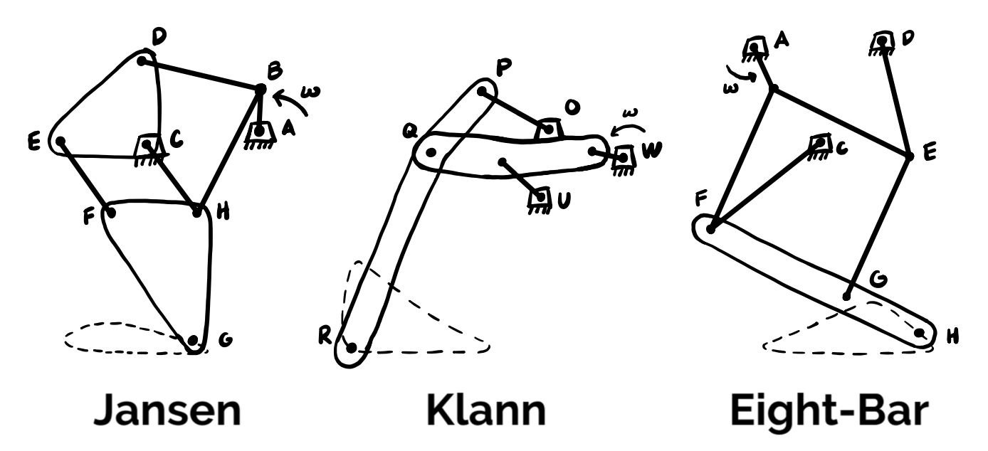
Three walking leg mechanisms achieve good gait profiles: Jansen's linkage, Klann's linkage, and a more recently established eight-bar mechanism. We chose to look at how changing the grounded joints' positions affected the gait profiles as we believed this would be the easiest aspect of the mechanism to change mechanically.
Jansen: Altering the position of the one grounded joint position the Jansen linkage has, we see that there does not seem to be much ability to change the stride length.
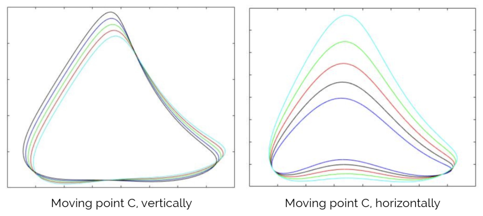
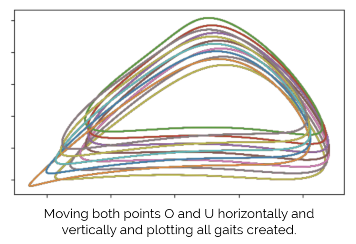
Klann: Altering the positions of both grounded joints the Klann linkage has, we see again that there is not much ability to change the stride length.
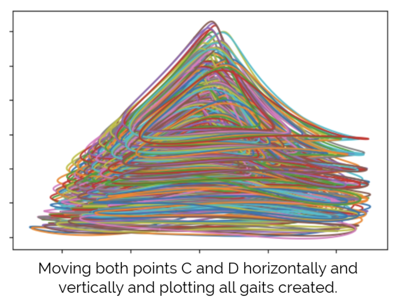
Eight-Bar: Altering the positions of both grounded joints the eight-bar linkage has, we see that there seems to be a wide spread of gait profile that can be created. This shows major potential to complete our objective but needs further analysis.
Analysis
We needed a more definite and visually comprehensive way to view how the position of the grounded joints affects the desired characteristics of the gait profile. The three characteristics that we care about are flatness, stride length, and stride height.
Flatness: If the bottom of the gait profile is not flat, the robot will bob up and down as it walks which will require extra work from the drive motor.
Stride Length: To steer with a smaller radius, we need the ratio of the long stride to the short stride to be large.
Stride Height: If the stride height changes, then the robot's body will tilt, putting unwanted lateral forces on the legs.
If we make heat maps of these three variables as a function of the grounded joint position, we can easily visualize the effect that it has on the overall gait profile and see what mechanical movement is necessary to achieve gaits that are flat, have a big change in stride length, and maintain consistent stride height.
Grounded Joint D: Looking at the heatmaps down below for each characteristic, we can see that there is a line that achieves good flatness and a relatively large change in stride length, however the stride height changes quite substantially. Due to the amount of tilting the robot would experience when turning, moving grounded joint D would not be a viable solution.

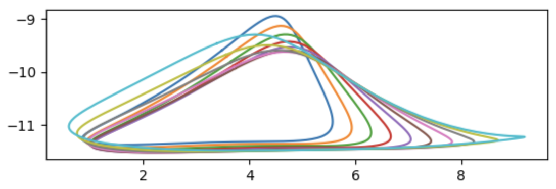
Grounded Joint C: Looking at the heat maps down below, we can see that there is an arced path that achieves good flatness, a large change in stride length, and maintains a consistent stride height. This looks to be our answer for mechanically altering the gait profile of the leg mechanism so that we can effectively turn!

Here are the gait profiles created as the position of grounded point C is placed along that arc.
Design and Fabrication
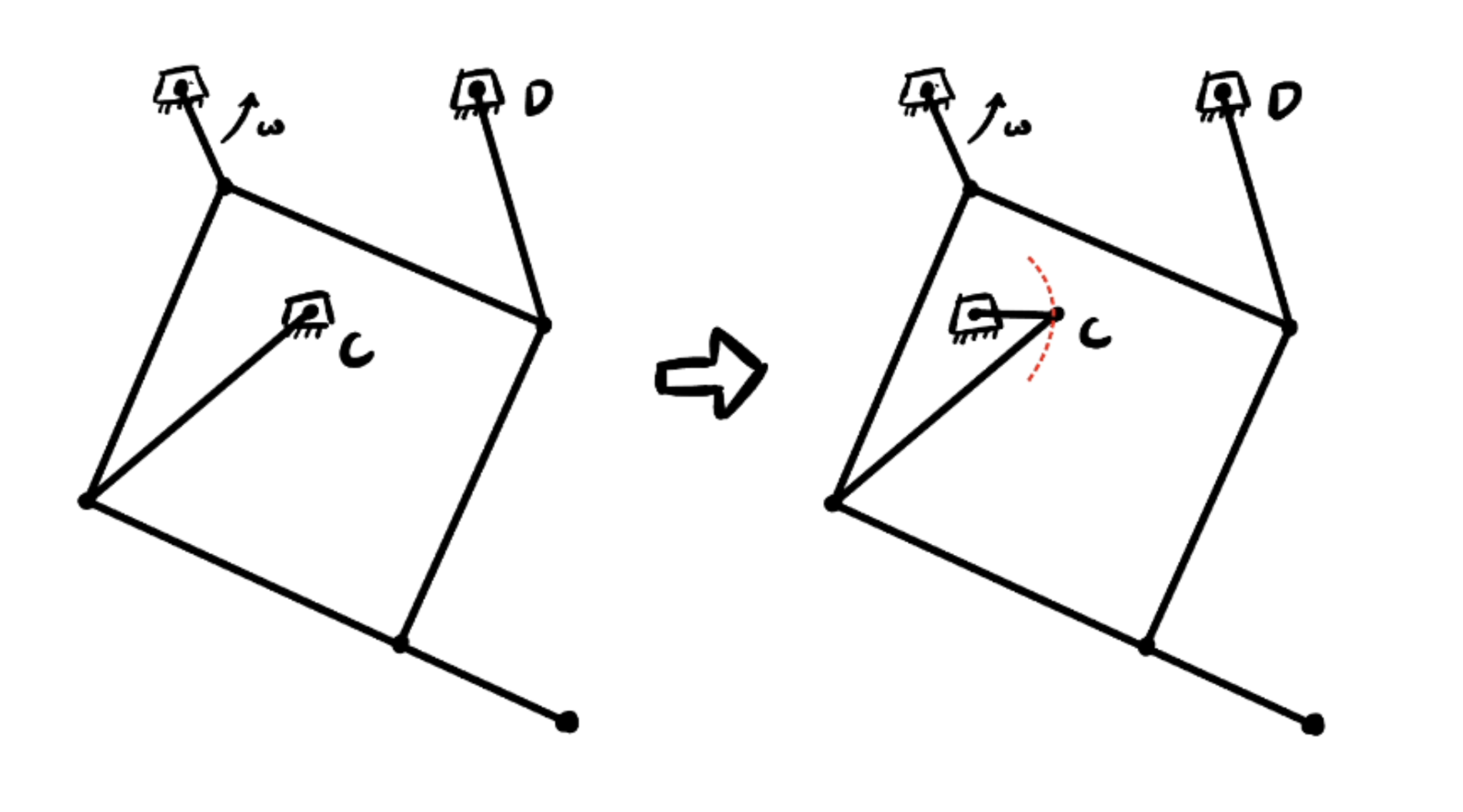
What the results of the analysis will look like mechanically is shown to the right. Notice that to move the position of C in an arc it would make sense to have another link added that is controlled by an actuator.
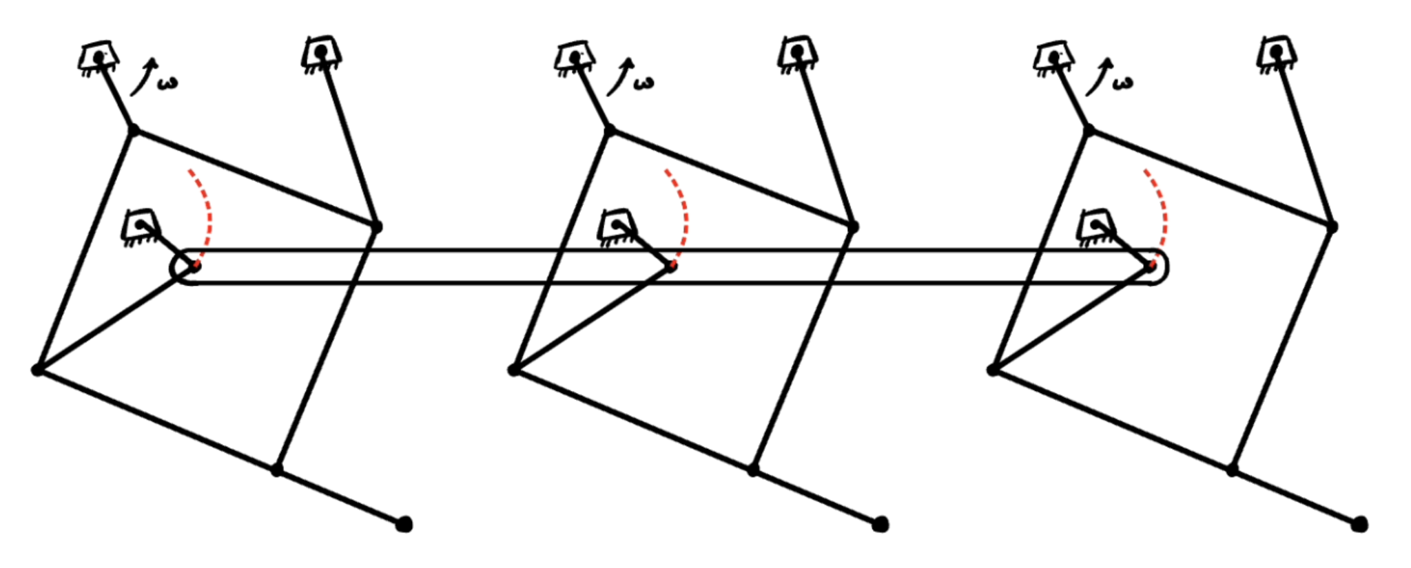
If we wanted to couple all three legs on one side so that they all have the same stride length, we could use a six-bar linkage to achieve that.
We want the grounded joint positions on each side to change in alternate directions along the arc as seen on the left. This will give us a long stride length on one side and a short stride length on the other.

Taking these mechanical design criteria and accounting for costs and functionality, this is the final CAD design we came up with for our robot.
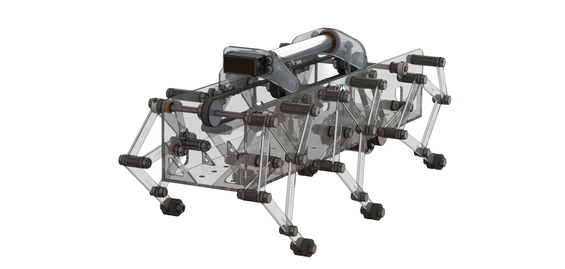
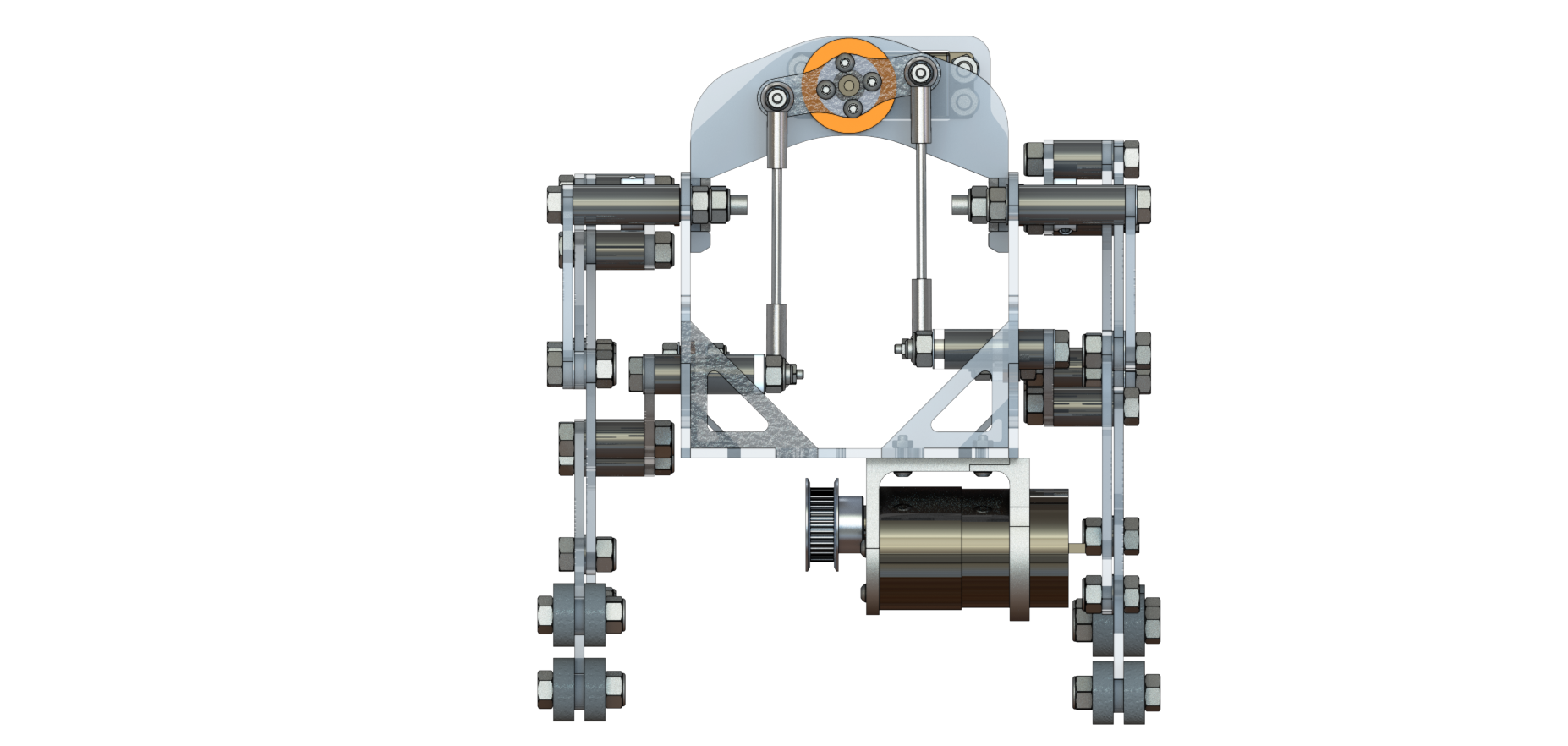

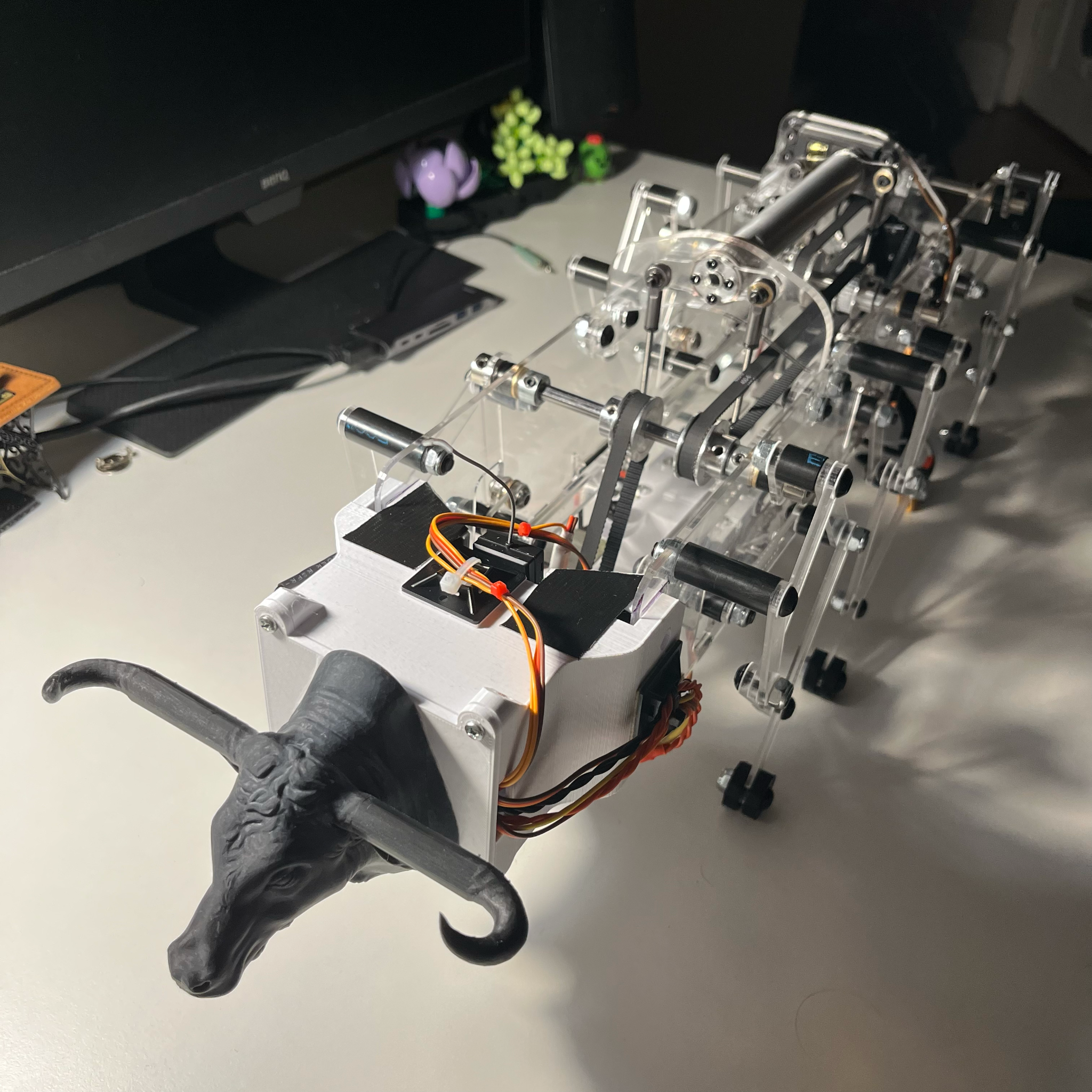
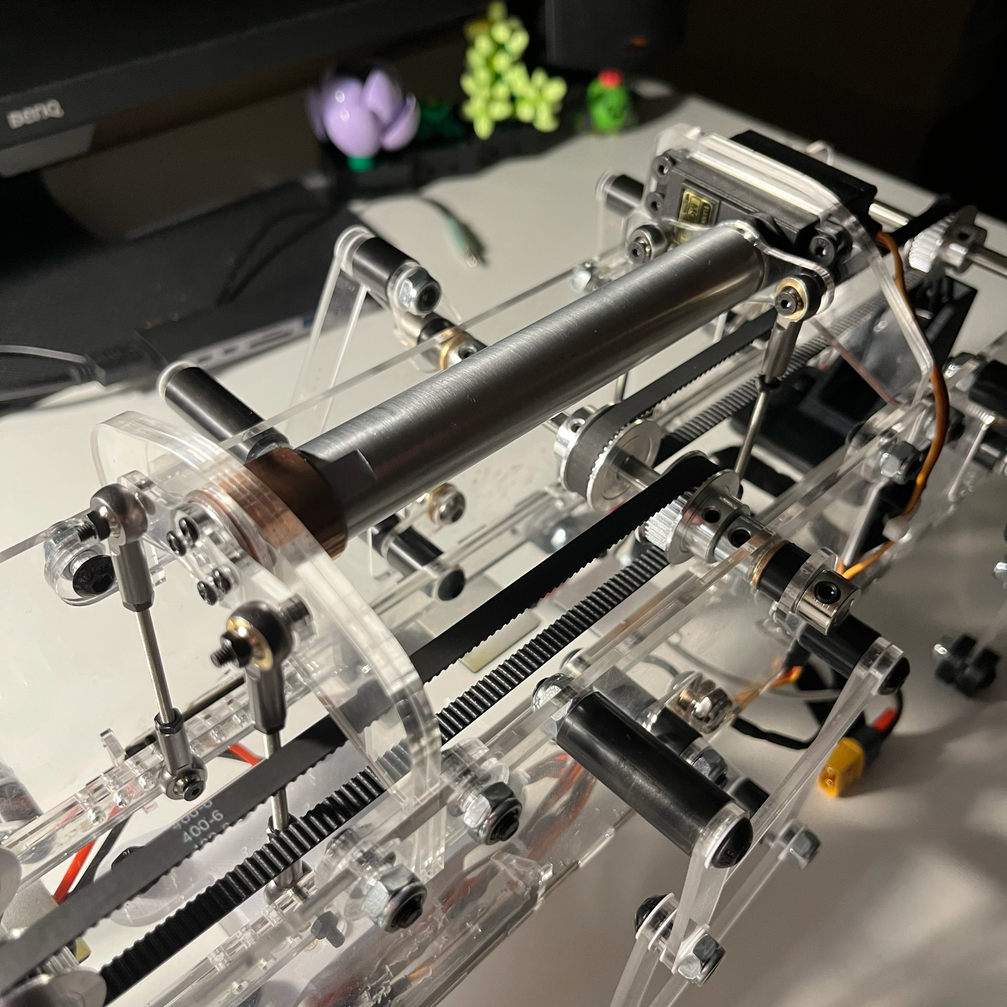
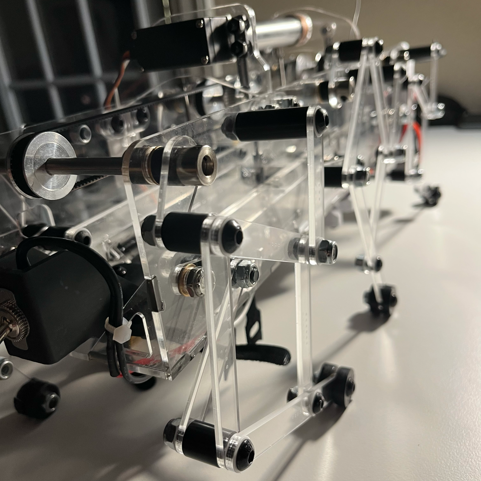
We designed this robot to be fabricated nearly entirely out of 3mm acrylic to make use of the time-friendly laser cutter. The drive motor is coupled to all six legs via three D-shafts, timing belts, and pulleys. The driving links of each leg have alternating D-profile to mechanically phase the appropriate legs 180 degrees apart. The two six-bars reside inside the robot's chassis and the steering system is made with a servo, hollow aluminum shaft, some laser-cut acrylic, and ball joints. The use of the shaft and a total of four ball joint connections is a design change that we had to make due to the lack of rigidity in the six-bar mechanism. There are no ball bearings used in this design. All joints were made with only bolts, low-friction PTFE washers, and machined Delrin spacers, except for some bronze bushings used for shaft bearings. Rubber washers were added to the feet to increase traction. The motor and servo are controlled via a microcontroller and transmitter/receiver system.
Before laser cutting all of our parts we made sure to cut some test holes for important tolerances to be hit, varying each hole dimension by a thousandth of an inch.
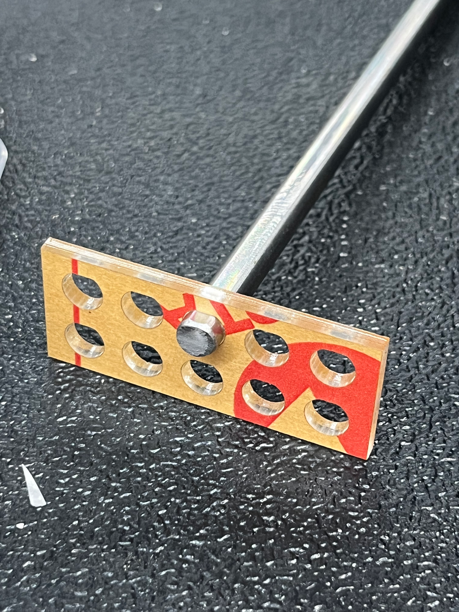
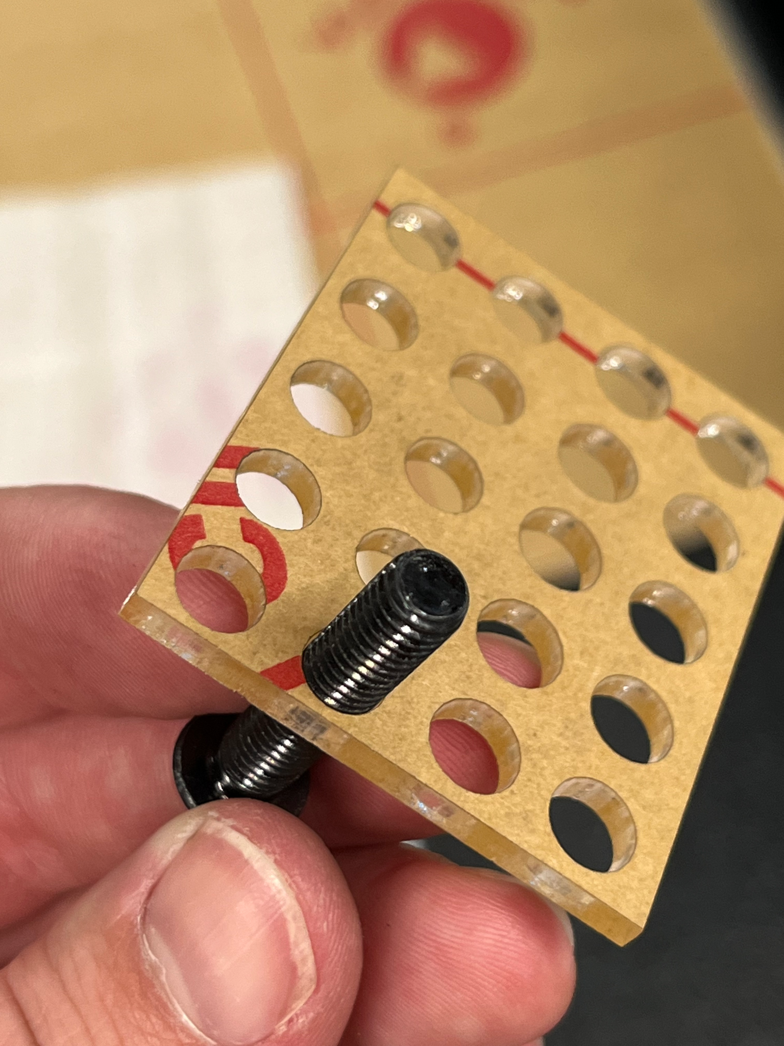
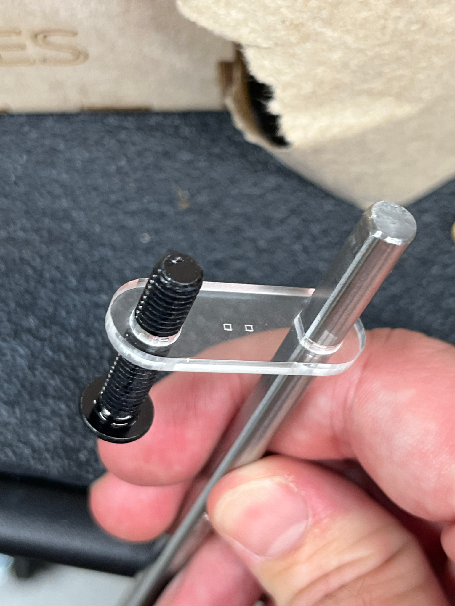
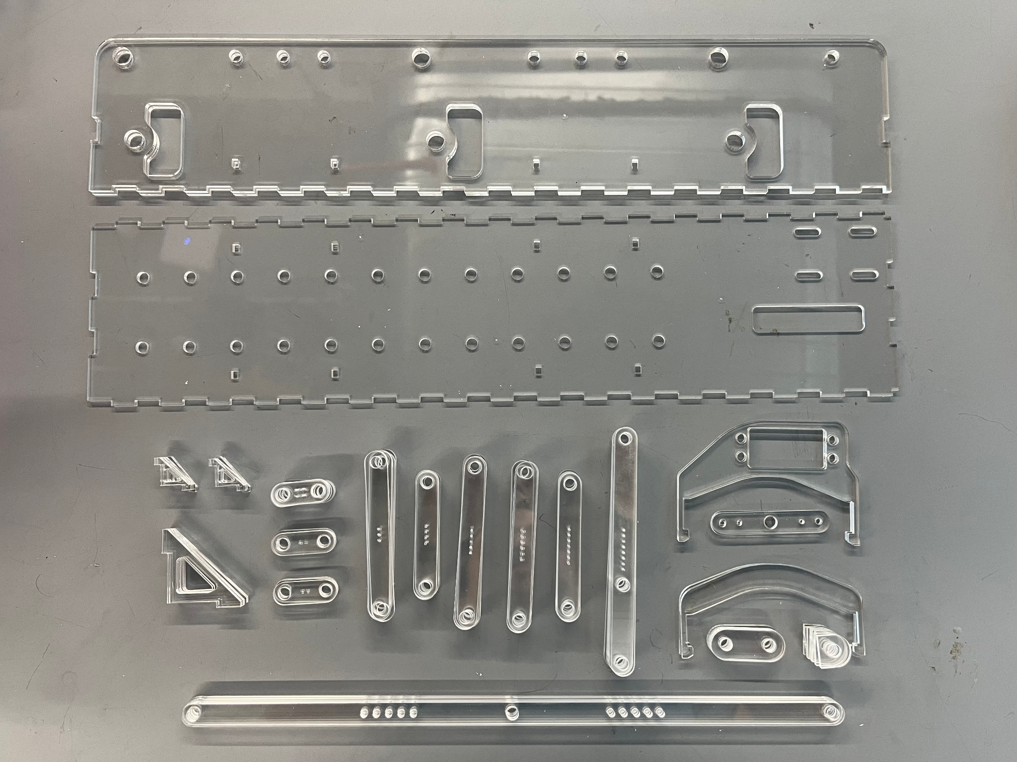
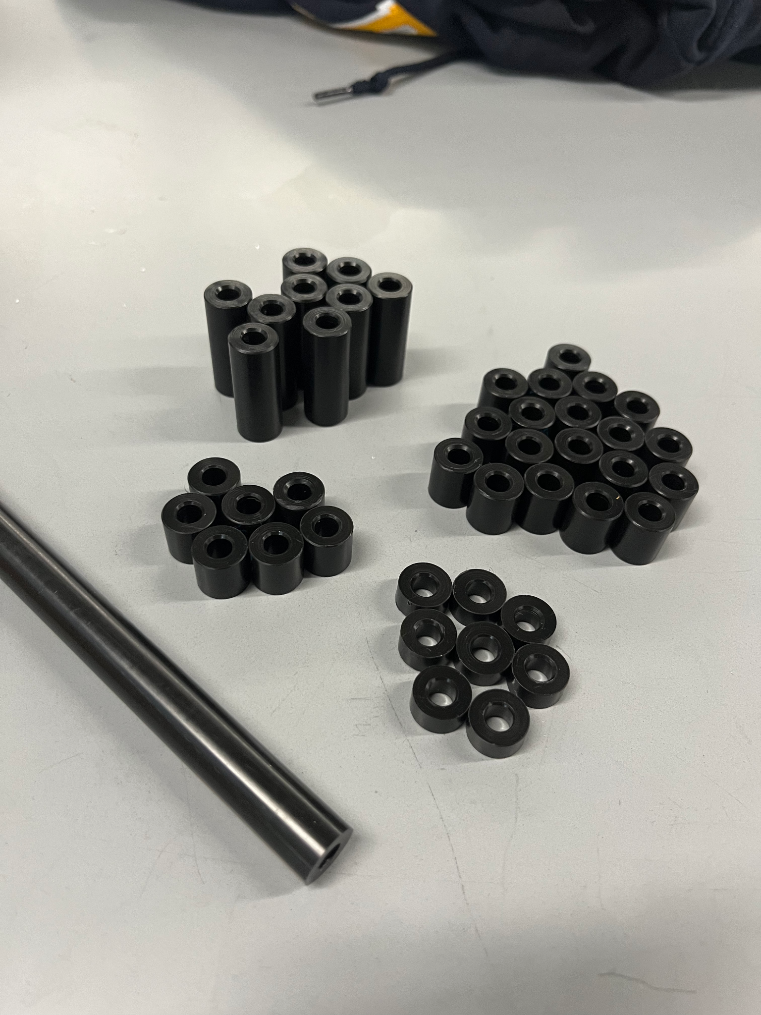
After many hours on the laser cutter and some time spent on the lathe, we had all of the fabricated parts needed to begin assembling.
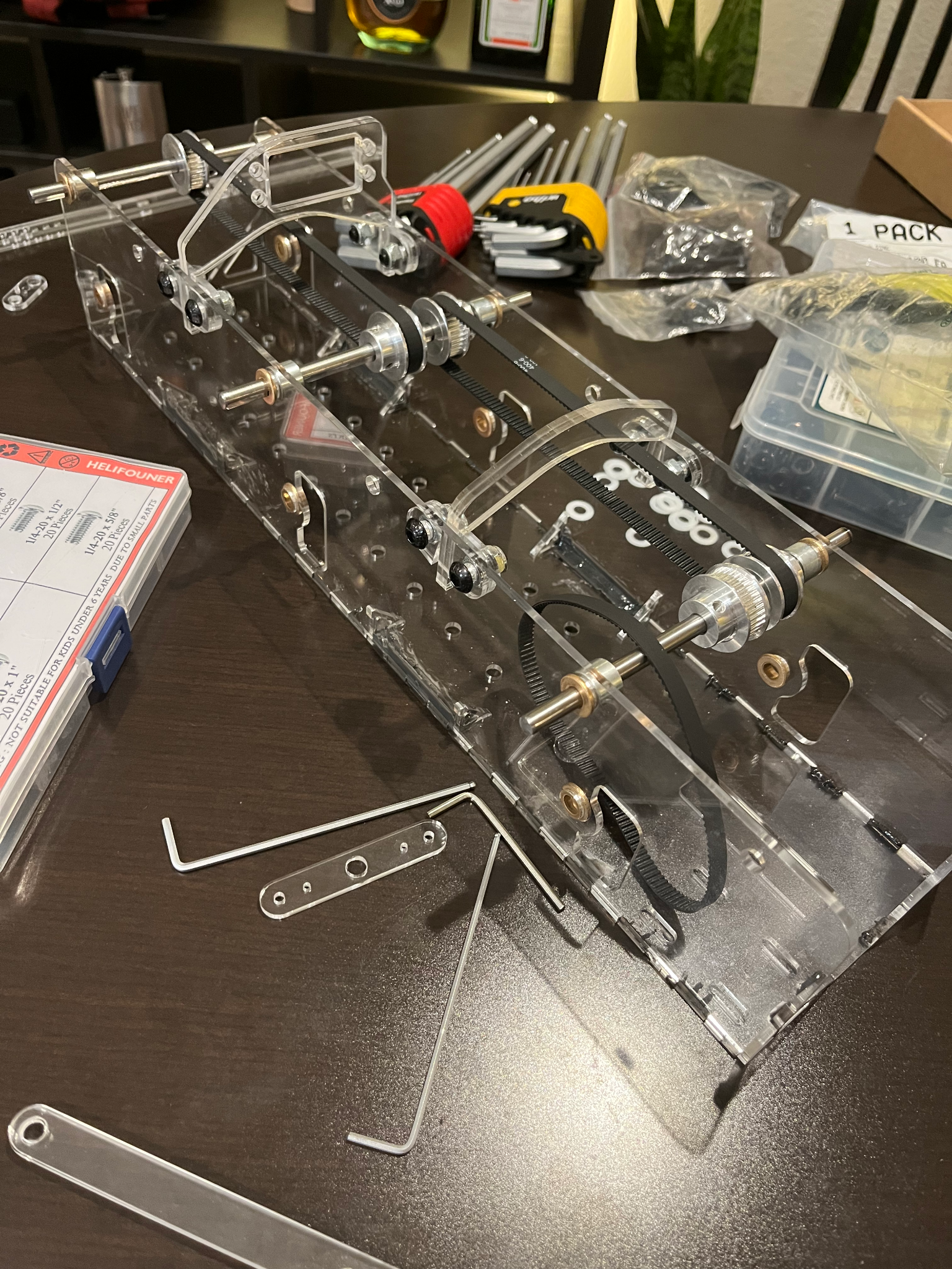
We began assembling the legs, ensuring the joints were tightened enough to remove axial play and only allow for low-friction rotational movement. Next, we assembled and epoxied the frame together.
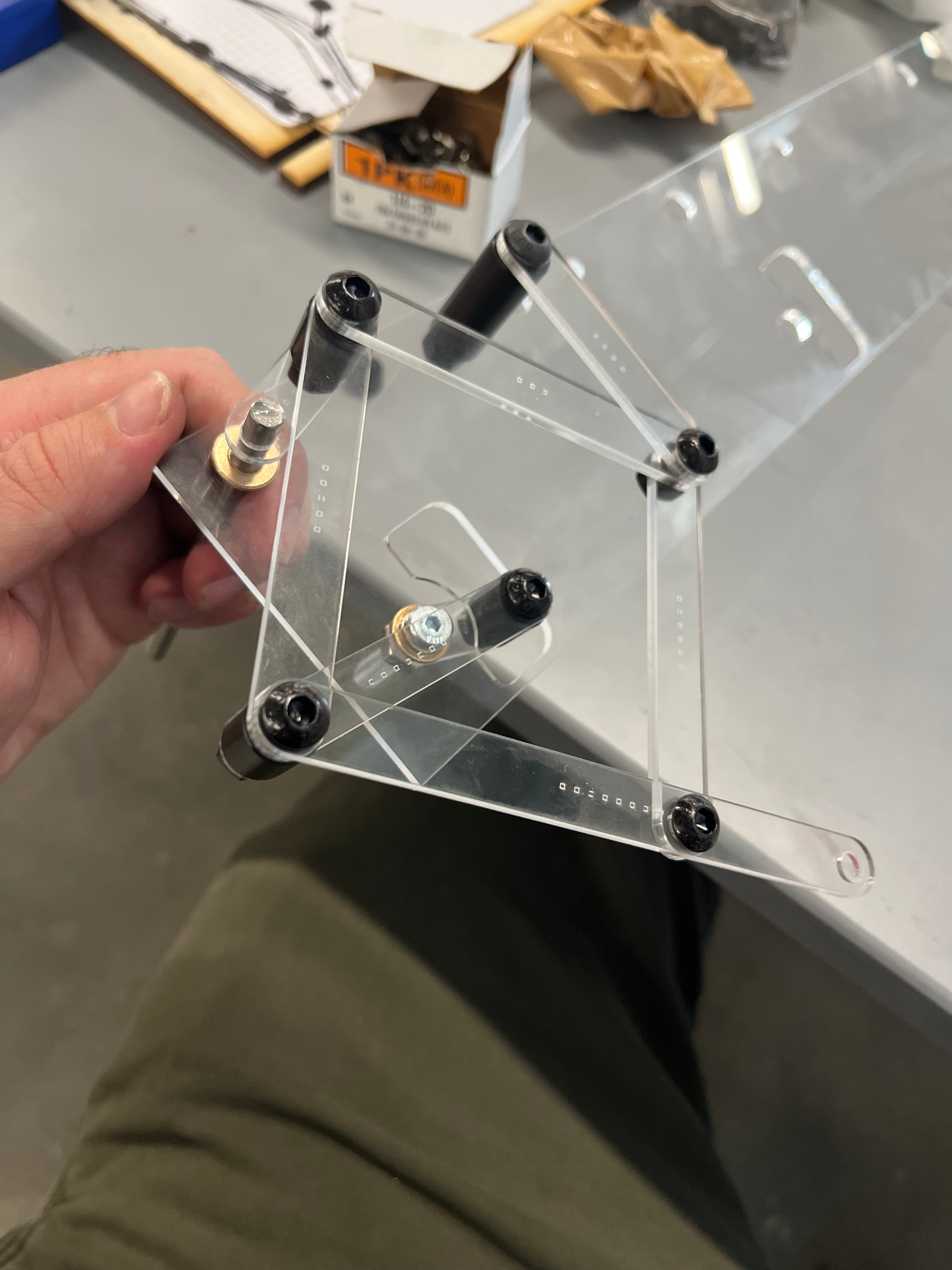
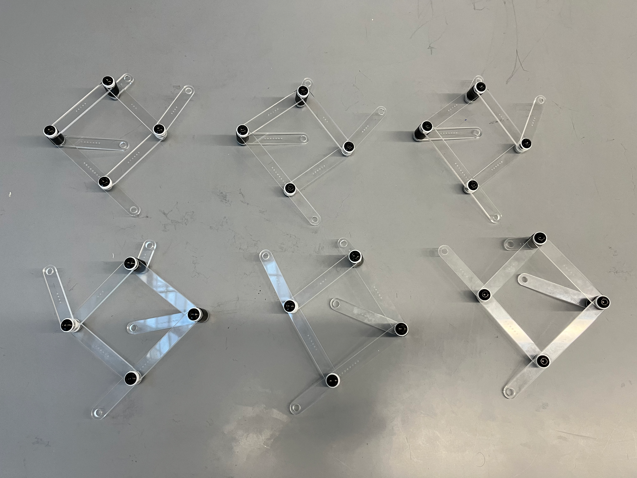
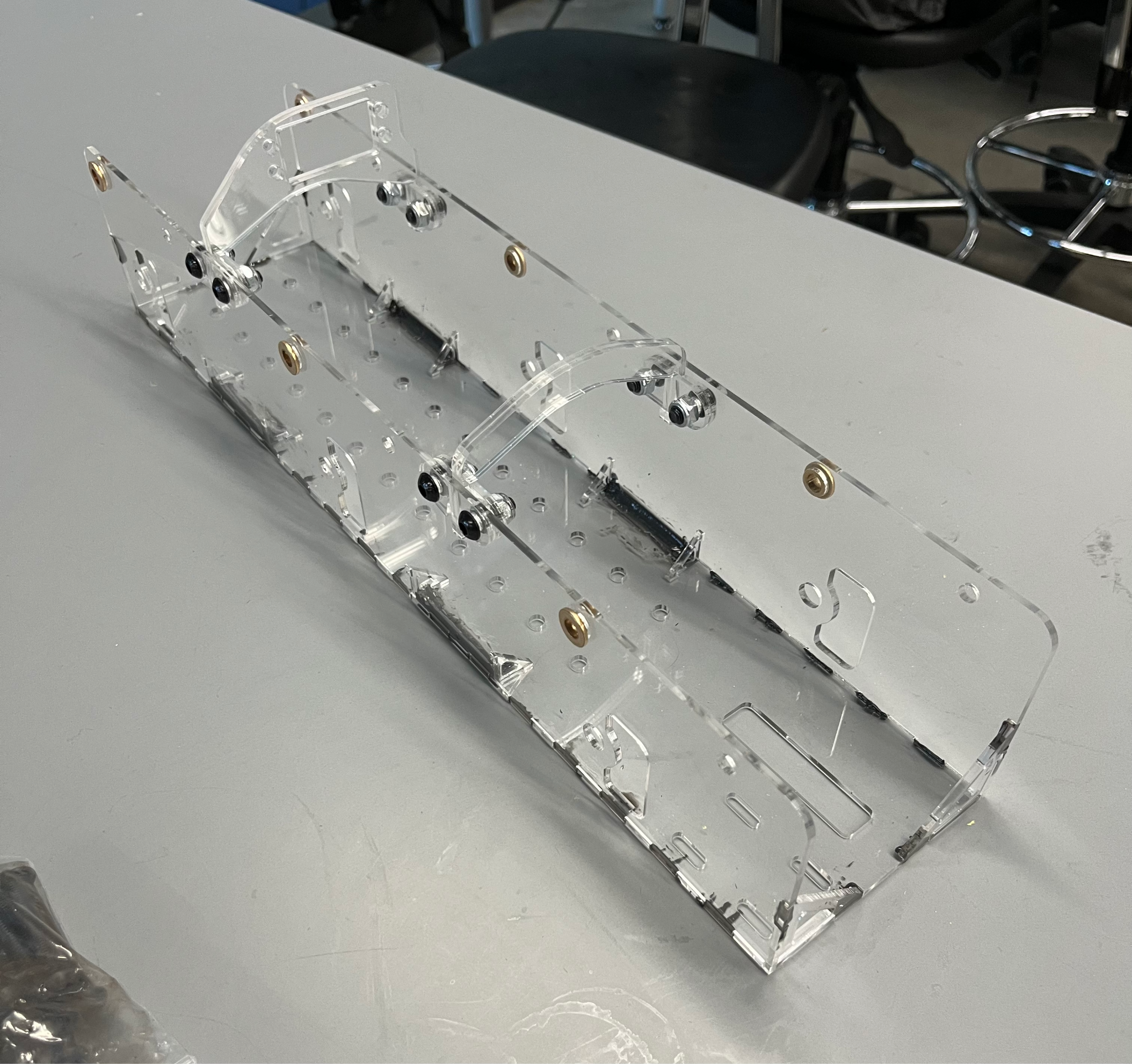
Assembling the rest of the hardware, steering system, motors, and electronics proved to be much harder than expected and was yet another lesson learned about designing for assembly.
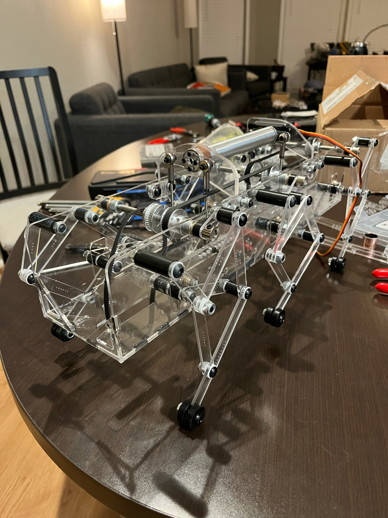
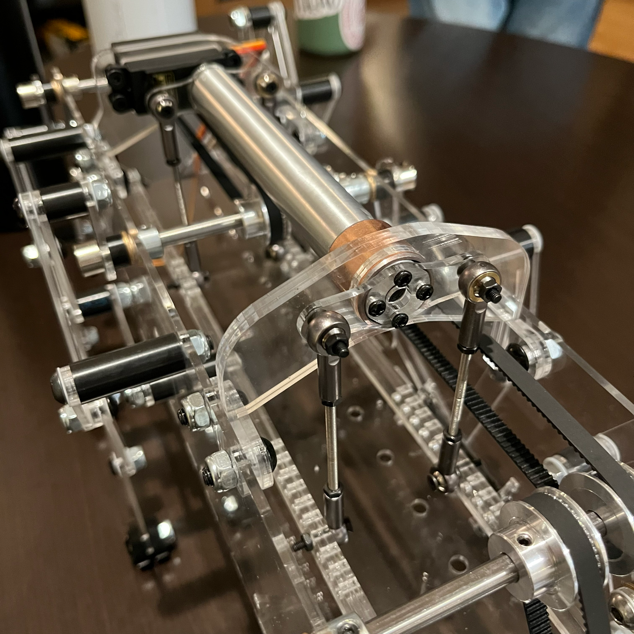
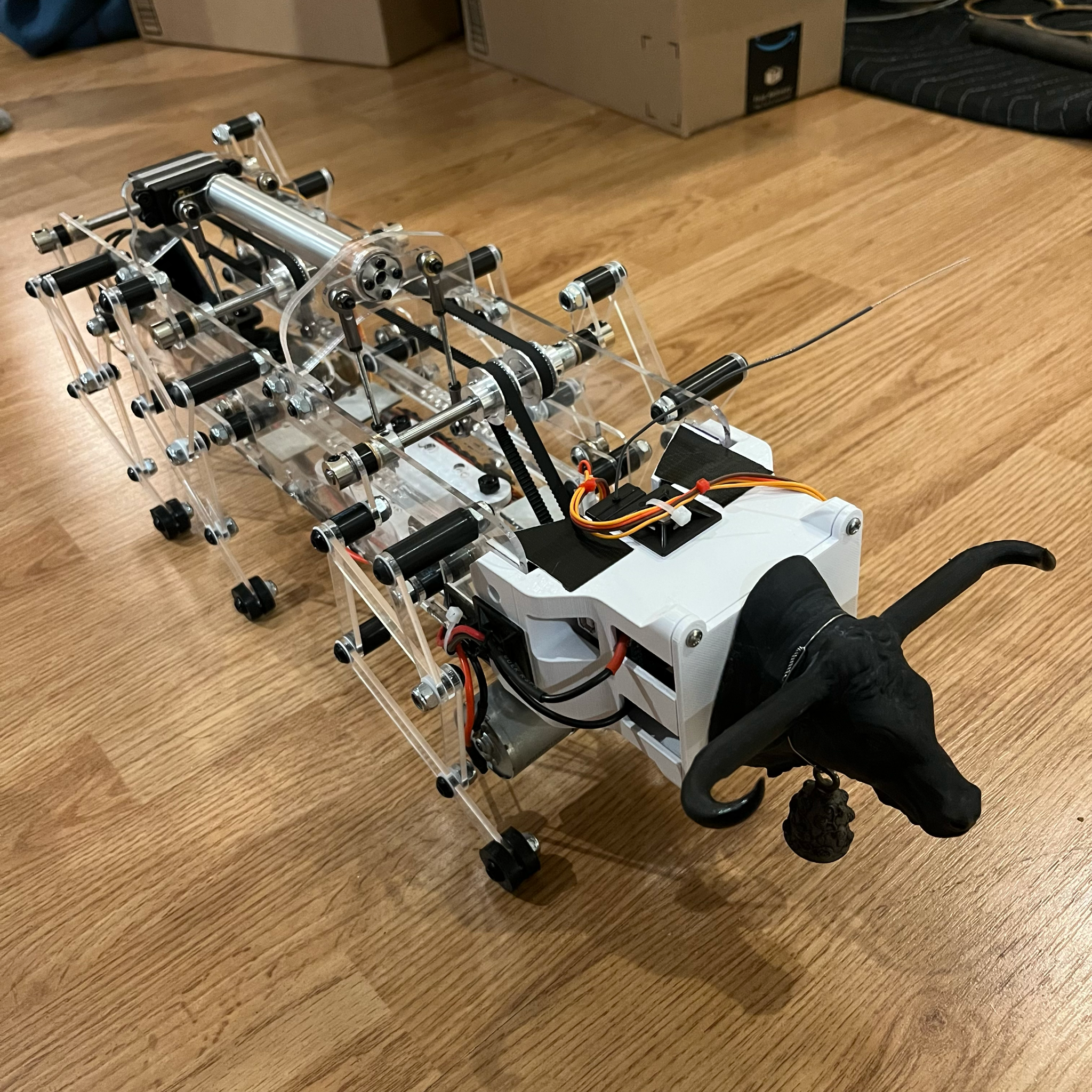
Final Build and Video Demonstration
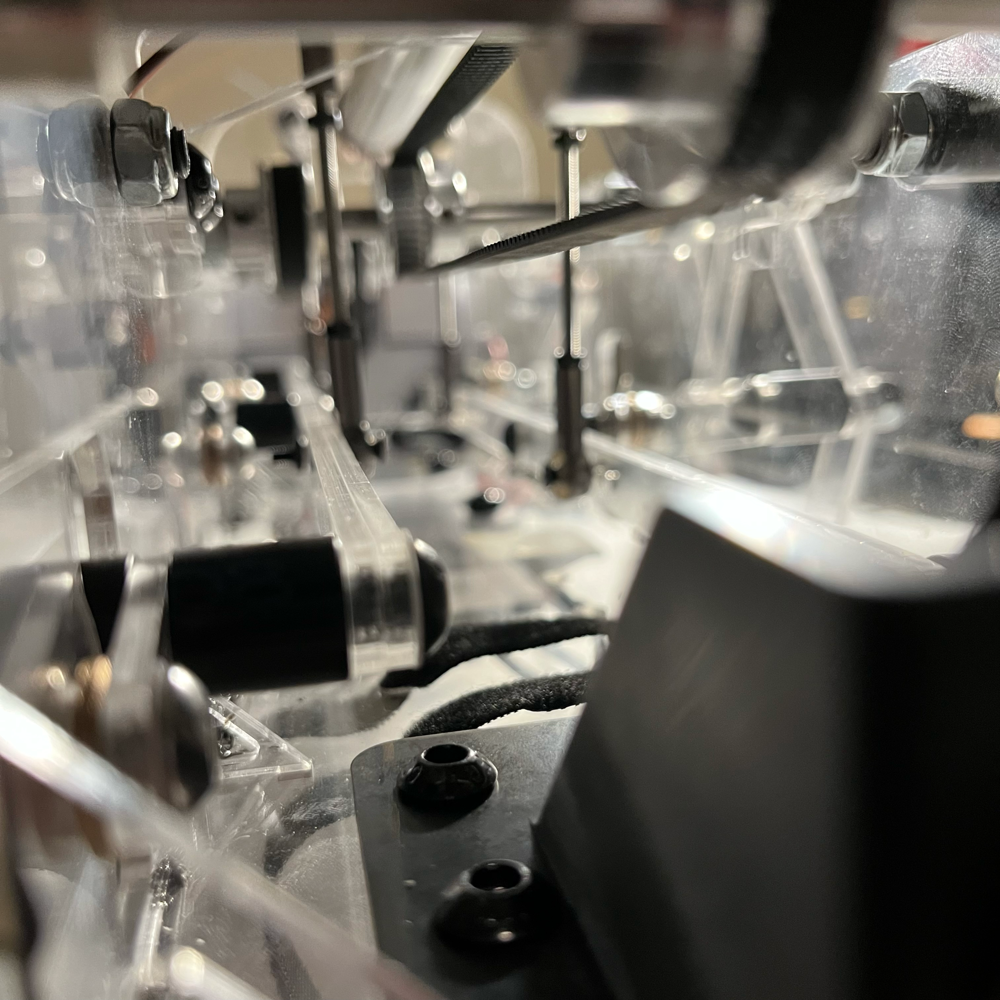
This project was a challenge and we are proud that it all came together like we expected it too. With that being said here are some nice pictures of our robot and a video demonstration showing its functionality.
